


4-14 Input / Output MN1921
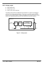
4.5.3 Error output
The NextMove ST control card has an internal error output connected directly to the enable
inputs of the ST L297 stepper controllers (see section 4.3.1). The error output must therefore
be used to enable the axes. There are a number of methods for controlling the error output.
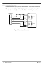
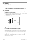
4.5.3.1 RELAY keyword
Because the NextMove ST control card is used in products that include a hardware relay, the
error output may be controlled directly by the RELAY keyword. The command RELAY=1 will
enable the stepper controllers; the command RELAY=0 will disable them.
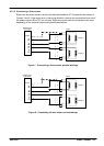
4.5.3.2 DRIVEENABLEOUTPUT keyword
The DRIVEENABLEOUTPUT keyword can be used to configure the error output as the drive
enable output. For example, the command DRIVEENABLEOUTPUT.1=_RELAY0 will mean
that the error output will be the drive enable output for axis 1. When axis 1 is enabled, the error
output will be activated and the axis enabled. If multiple axes are configured to use the error
output as their drive enable output, enabling one axis will enable all of them. Similarly, if one
axis is disabled, all will be disabled.
The RELAY keyword cannot control the error output if it is configured as a drive enable output.
4.5.3.3 GLOBALERROROUTPUT keyword
By default, the error output is used as the global error output. In the event of an error on any
axis, the global error output will be deactivated, disabling all axes. This action overrides the
state of the error output defined by other methods, such as the drive enable status or RELAY
keyword. Alternatively, the GLOBALERROROUTPUT keyword can be used to configure a
general purpose digital output to be the global error output.
See the MintMT help file for details of each keyword.
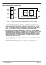
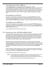
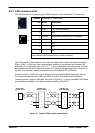
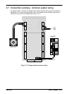
4.5.3.4 Jumper settings
The operation of the error output is dependent on jumpers JP1, JP3, JP4 and JP5. Jumper
JP1 is situated next to the POWER IN connector on the baseboard, and must be set as shown
in Figure 14.
JP1 JP1
Normal operation.
Stepper controller enabl e
inputsareunderthecontrol
of the NextMove ST Error
output.
Disable.
Steppercontroller outputs
are permanently disabled.
JP3 (do not fit)
JP4
JP5 JP1
Figure 14 - Error output jumper JP1
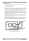
Jumpers JP3, JP4 and JP5 are situated at the edge of the NextMove ST control card, near the
end of the 50-pin expansion header. JP4 and JP5 must be fitted to allow correct operation of
the error output. The neighboring jumper JP3 must not be fitted.