


Input / Output 4-19MN1921
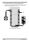
4.7 Connection summary - minimum system wiring
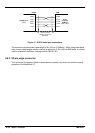
As a guide, Figure 17 shows an example of the typical minimum wiring required to allow the
NextMove ST to control a single stepper motor. The diagram shows the logic supply being
derived from the main Drive supply (see section 4.2.1).
Host PC
Serial
communic ation
Drive
power
supply
5
4
2
1
Steppermotor
Figure 17 - Example minimum system wiring