


9
TOOLS REQUIRED
The following tools and materials are required for a proper installation of the GS4000.
1. Wire cutter, stripper and crimping tools. (For attaching accessory equipment to the control
box barrier strip.)
2. A #2 Phillips Head screw driver for removing the screws to the High Voltage cover.
3. Medium standard straight blade screw driver for the terminal strip screws.
4. Very small blade screwdriver. (For adjusting the potentiometer on the Logic and Power board.)
5. Electric arc welder or an electric drill with a 3/8" bit. (For attaching Arm Bracket to the Gate.)
6. Several feet of #18 or #22 gauge insulated multistrand wire. (For connecting accessory
equipment to the control box terminal strip, and for limit switch control wires.)
7. Four 1/2" diameter concrete "redhead" bolts with hex nuts, flat washers and lock washers.
(For attaching the GS4000 to the concrete pad.) (Not Included)
8. Concrete drill and bit. (To drill mounting holes for concrete bolts.)
9. Multimeter. (To test line voltage and other measurements as necessary.)
10. Small level. (To level GS4000 at installation.)
11. Torque Wrench and 1-5/8” Socket
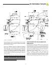
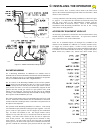
Mechanical Unit
Electrical Unit
Wood Pallet with 4 lag bolts
Instruction Kit
Instruction Manual
Warning signs
Swing Arm Kit
Swing Arm
Crank Arm
Crank Arm Extension
Swing Gate Fittings
Swing Arm Bracket
Swing Arm Padlock with keys
Hardware Package
The GS4000 as shipped consists of the components listed below.
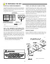
UNPACKING
CHECKLIST
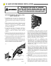
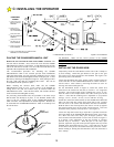
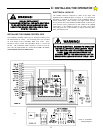
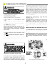
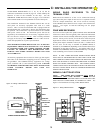
C: INSTALLING THE OPERATOR