


19
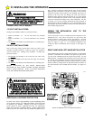
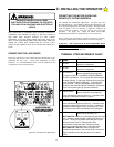
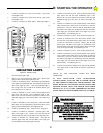
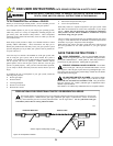
SETTING THE LIMIT SWITCHES
With the cover removed from the GS4000 MECHANICAL UNIT,
and the arm connected to the gate as well as to the GS4000 Operator,
position the gate at its FULLY CLOSED position. Identify the
lower Limit Switch. Loosen the clamping nut on the Limit Switch
Cam for the lower Limit Switch. Rotate the cam on the output shaft
until it engages the Limit Switch and an audible “click” is heard.
Repeat this several times until you are confident that the position of
the cam is such that the Limit Switch is just closed. Carefully tighten
the nut on the Limit Switch Cam. Snug the set screw on the cam
against the output shaft to protect the cam from accidental
movement. Open the gate to its FULLY OPEN position. Repeat
this procedure for the upper Limit Switch and Cam. (See Figure 21.)
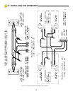
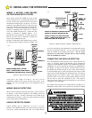
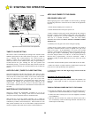
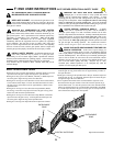
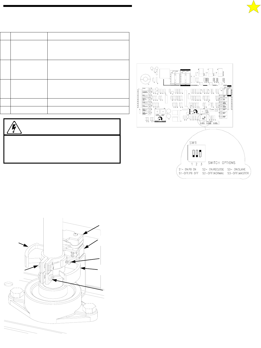
SETTING THE SWITCH SELECTABLE OPTIONS
The switches that control the selectable options are located on the
Control board. See Figure 22.
NO-LOAD TEST MODE
To run/test the GS4000 operator when it is not connected to a gate
leaf, turn all of the switches to the “ON” position. The GS4000 can
then be operated without a gate leaf attached for 20 complete cycles.
If more that twenty cycles are attempted in the test mode the operator
control board changes to a “sleep” mode and a low pulsed tone is
heard from the audible output. You can reset the operator for a
renewed 20 test cycles by turning the power off and back on again.
To return to normal operation turn one of the switches to the “OFF”
position, then set all the switches to the desired mode of operation as
described in the text that follows.
OPEN/CLOSE PUSH BUTTON ENABLE/
DISABLE (PATENT NO. 6,611,205)
Switch S1 controls the Push Button Enable/Disable Feature.
SWITCH 1 OFF: Activating the Open or Close buttons the gate will
open or close fully. Activation of the Open while the gate is closing
will cause it to re-open. Activation of the Close while the gate is
opening has no effect. Continuous activation of an opposing button
while the gate is on a limit will prevent operation in that direction.
Continuous signal required to move the gate when in the alarm mode.
SWITCH 1 ON: Gate does not respond to pushbutton input when in
the normal mode. Continuous signal required to move the gate when
in the alarm mode. This patented feature allows you to mount a two
or three button station in an unsecured location as it will only be
active when in the alarm mode.
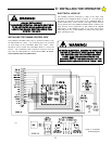
WARNING!
RISK OF ELECTROCUTION
DO NOT BEGIN TO SET THE FOLLOWING
ADJUSTMENTS UNTIL THE POWER IS TURNED
OFF AT THE GS4000 CONTROL BOX
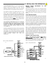
D: STARTING THE OPERATOR
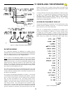
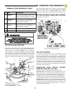
# NAME
DESCRIPTION
18 OPEN LIMIT
SWITCH
Connection for Limit Switch Input — See
page 13, Fig. 13 or page 14, Fig. 15, for
Limit Switch Wiring (single or bi-parting)
M2 MOTOR RUN
WINDING
Connection for Motor wiring - See
Section C. Figs. 13 or 15 for Motor
Wiring (single or bi-parting)
M1 MOTOR RUN
WINDING
Connection for Motor wiring - See
Section C. Figs. 13 or 15 for Motor
Wiring (single or bi-parting)
L2 AC INPUT
Also connection for MOTOR COMMON
L1 AC INPUT
UPPER LIMIT
SWITCH
LOWER LIMIT
SWITCH
SET SCREW
LOWER LIMIT
CAM
LOWER
LIMIT CAM
CLAMPING
NUT
UPPER
LIMIT CAM
CLAMPING
NUT
UPPER
LIMIT
CAM
106304
Figure 21: Limit Switches
TERMINAL STRIP REFERENCE CHART
ABLE OPTIONS
SWITCH SELECT-
LOCATION OF
110126
Figure 22: SETTABLE SWITCHES