


15
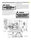
CLOSE/OPEN PHOTO/EDGE (#s 9, 10, 12, & 13) can be
continuous commands as noted on page 18. Labels identify the
function of each of the terminals on the strip. See the
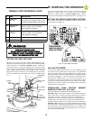
TERMINAL STRIP Reference Chart on pages 17-19 related to
each terminal number for an explanation of each of the inputs.
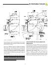
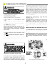
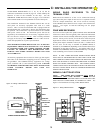
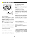
The transformer mounted in the GS4000 Control Box can be
used power an accessory equipment item such as a radio
receiver. This is a Class II transformer and is equipped with an
internal fusible link. If this link is "blown" the transformer must
be replaced. The transformer is powered whenever the GS4000
main power switch is ON. The maximum power that can be
supplied by the transformer for an accessory equipment item is
20 VA or about 1 Ampere at 24VAC
. This is usually sufficient
to supply an accessory equipment item such as a radio receiver.
Check the equipment for its power specifications.
THE MAXIMUM POWER DRAW FOR ALL AUXILIARY
EQUIPMENT SHOULD NOT EXCEED 20 VA IF POWER
IS SUPPLIED FROM THE GS4000 CONTROL BOARD.
FAILURE TO OBSERVE THIS RESTRICTION WILL
DAMAGE THE GS4000 CONTROL BOARD AND VOID
ANY WARRANTY.
All auxiliary equipment devices must be of the type that require
both sides of the transformer supplying power be "floating" and
not grounded. The GS4000 auxiliary equipment low voltage
power, terminals 1 & 2, is not referenced to ground. FAILURE
TO OBSERVE THIS RESTRICTION WILL DAMAGE THE
GS4000 CONTROL BOARD AND VOID ANY
WARRANTY.
WIRING RADIO RECEIVERS TO THE
TERMINAL STRIP
Radio Receivers MUST be of the 4 wire connection hook-up
type (where the power input for the receiver is separate from the
receiver’s output connection). The 4 wire version is necessary
as the GS4000 control board 24 VAC output is not referenced to
ground. See Figure 16 and the following text for proper
connection.
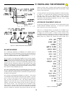
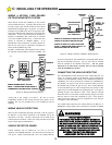
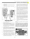
FOUR WIRE RECEIVERS
Four wire receivers replace the "spade" terminals on the RECEIVER
with 4 wires. These wires are typically color coded. The instructions
with the receiver must be carefully followed to properly connect the
receiver. For any 4 wire receiver, two of the wires will be for power
input and two will be for the relay contacts. Connect the two wires
for the power input to terminals 1 and 2 (24 VAC). Connect one of
the two wires for the relay to terminal #4 (RADIO OPEN) or
terminal #3 (ALTERNATE) depending on the function desired (see
descriptions on the chart on pages 17 - 19) and the other wire to
terminal #16 (COMMON) on the GS4000 terminal strip. See Figure
16 for connecting 4 wire receivers to the GS4000.
NOTE: IF THE 4 WIRE RECEIVER INSTRUCTIONS SHOW
THAT TWO OF THE WIRES ARE OF THE SAME COLOR AND
ARE COMMON CONNECTIONS INSIDE THE RECEIVER, YOU
WILL NOT BE ABLE TO UTILIZE THIS RECEIVER AS WIRED
WITH THE GS4000 CONTROL BOX. THE POWER SUPPLY
CONNECTIONS MUST BE SEPARATE FROM THE RECEIVER
OUTPUT CONNECTIONS WITH NO COMMON REFERENCES
INSIDE THE RECEIVER.
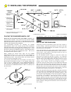
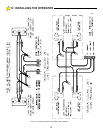
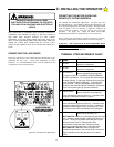
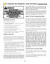
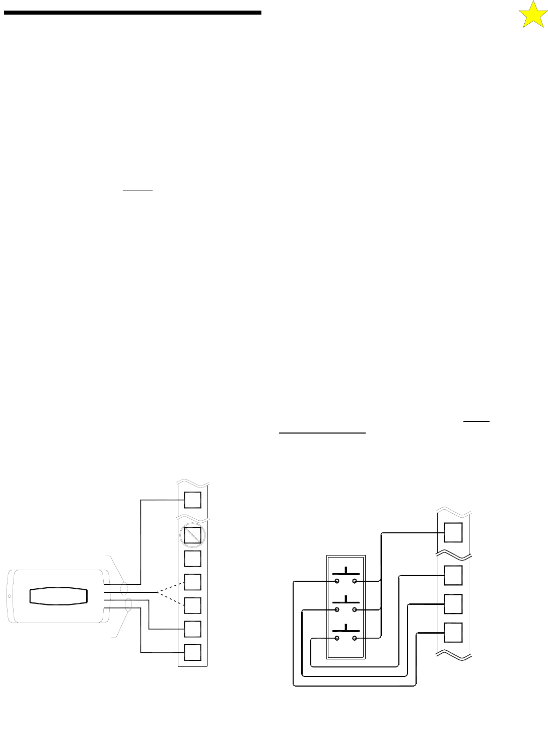
WIRING A 3-BUTTON STATION
NOTE: THE GS4000 WILL OPERATE ONLY WITH A
NORMALLY OPEN STOP BUTTON. THREE BUTTON
STATIONS MAY BE ORDERED FROM ALLSTAR WITH THE
STOP BUTTON CONFIGURED AS NORMALLY OPEN. See
Figure 17 for instructions on wiring a Three Button Station.
C: INSTALLING THE OPERATOR
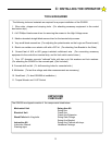
WIRING FOUR-WIRE RECEIVER
FOR RECEIVER
24VAC POWER
DRY CONTACT
RELAY OUTPUT
2
1
3
4
24 VAC
24 VAC
ALTERNATE
RADIO OPEN
STRIP
TERMINAL
16
6
5
COMMON
FREE EXIT
OPEN
Figure 16: Wiring 4-Wire Receiver
110120
OR
CONNECT TO:
WITH NORMALLY OPEN STOP
WIRING 3-BUTTON STATION
OPEN
STOP
CLOSE
6
7
OPEN
CLOSE
8
16
STRIP
TERMINAL
STOP
COMMON
Figure 17: Wiring 3-Button Station
110121