


21
3. Connect to Terminal #17, Close Limit Switch: Close Limit
Switch light is ON.
4. Connect to Terminal #18, Open Limit Switch: Open Limit
Switch light is ON.
5. Connect to Terminal #4, Radio Open.: Radio Open light is
ON, Motor Open light is ON.
6. Remove wire from Terminal #4, Radio Open. Radio Open
light goes OUT, Motor Open light stays ON.
7. Connect to Terminal #8, Stop : Both Motor Open and Motor
Close lights are momentarily ON, then both Motor Open and
Motor Close lights go OUT. The Stop Pushbutton light is
ON as long as the wire is held on the terminal and the goes
OUT when the wire is removed.
8. Connect to Terminal #7, Close: Observe that the Motor Close
light comes ON and the Close Pushbutton light is ON.
Remove the wire from terminal #7 and observe that the Close
Pushbutton light goes OUT and the Motor Close light stays
ON.
9. Connect to Terminal #11, Reversing Loop,: Observe that both
Motor lights are ON momentarily and then the Motor Close
light goes OUT and the Motor Open light stays ON.
10. Connect to Terminal #8, Stop,: Same as above, Sequence 5.
11. Connect to Terminal #3, Alternate: Alternate light is ON,
Motor Close light is ON. Remove wire and note that the
Alternate light goes OUT but the Motor Close light stays ON.
12. Connect to Terminal #3, Alternate again: Note that the
Alternate light comes ON, that the Motor Close light goes
OUT and that the Motor Open light comes ON.
13. Connect to Terminal #6, Open: Observe that the Motor Open
light comes ON and the Open Pushbutton light is ON.
Remove the wire from terminal #6 and observe that the Open
Pushbutton light goes OUT and the Motor Open light stay
ON.
14. Connect to Terminal #12, Open Contact Sensor: Note that the
Open Contact Sensor light comes on & remains on until the
connection is removed. Observe that the both Motor Open
and Motor Close lights are momentarily ON, then the Motor
Open light goes out and the Motor Close light stays on for
approximately 1 second then goes out.
15. Connect to Terminal #7, Close: Same as above Sequence #6.
16. Connect to Terminal #10, Close Non-contact Sensor: Note
that the Close Non-contact Sensor light comes on & remains
on until the connection is removed. Observe that the both
Motor Open and Motor Close lights are momentarily ON,
then the Motor Close light goes out and the Motor Open light
stays on for approximately 1 second then goes out.
17. Connect to Terminal #7, Close: Same as above Sequence #6.
18. Connect to Terminal #13, Close Contact Sensor: Note that the
Close Contact Sensor light comes on & remains on until the
connection is removed. Observe that the both Motor Open
and Motor Close lights are momentarily ON, then the Motor
Close light goes out and the Motor Open light stays on for
approximately 1 second then goes out.
19. Connect to Terminal #9, Shadow Loop: Note that the Shadow
Loop light comes on and remains on until the connection is
removed.
CHECK OF THE INDICATOR LAMPS HAS BEEN
COMPLETED.
IF THE INDICATOR TEST PERFORMED
SATISFACTORILY, TURN OFF THE AC POWER SWITCH
AT THE GS4000 CONTROL BOX AND RECONNECT THE
WHITE HIGH VOLTAGE HARNESS CONNECTOR TO THE
CONTROL BOARD. RESET THE SWITCH SELECTABLE
OPTIONS (S1, S2, S3) TO THE APPROPRIATE SETTINGS
AS PER THE FUNCTIONS DESIRED (SEE PAGE 19 AND 20).
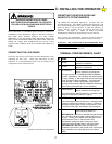
WARNING!
RISK OF ENTRAPMENT
OVERLOAD SENSITIVITY HAS NOT BEEN SET.
DO NOT ALLOW ANYONE NEAR THE GATE AND
DO NOT LEAVE GATE AND GS4000 UNIT
UNATTENDED UNTIL FOLLOWING PROCEDURES
HAVE BEEN COMPLETED.
USE CAUTION DURING THIS FINAL
ADJUSTMENT PERIOD.
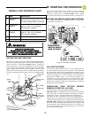
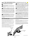
D: STARTING THE OPERATOR
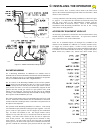
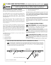
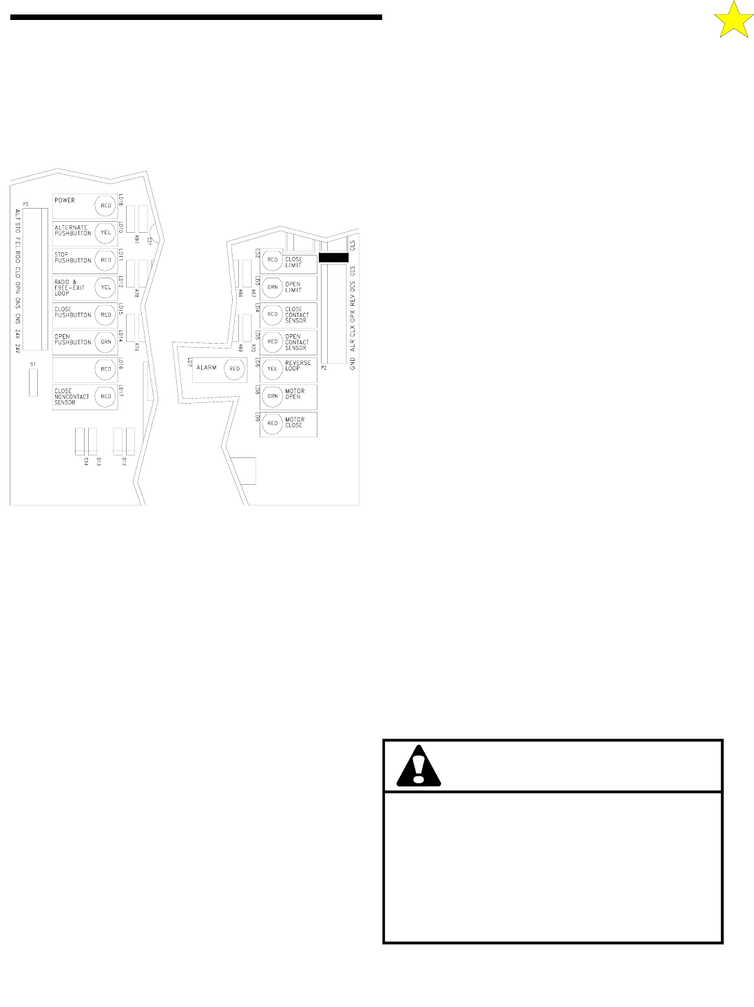
INDICATOR LAMPS
110127
Figure 24: Indicator Lights
SHADOW
LOOP