


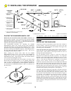

18
# NAME
DESCRIPTION
7 CLOSE
Momentary or continuous signal. On/
Off mode set by Switch #1
WITH SWITCH 1 OFF: Once activated the gate will
close fully. Activation while the gate is opening has no
effect. Continuous signal required to move the gate
when in the alarm mode.
WITH SWITCH 1 ON: Gate does not respond to
pushbutton input when in the normal mode. Continuous
signal required to move the gate when in the alarm
mode.
8 STOP
Momentary or continuous signal.
Overrides all other signals. Once activated, the gate will
immediately stop and await a new command. If the
STOP input is continuously activated, the gate will not
move.
9 SHADOW LOOP
Momentary or continuous signal.
This input is active only when the gate is at rest in the
fully OPEN or CLOSED position, it has no effect on the
gate when closing or opening. Continuous activation will
prevent the gate from moving in the open or close
direction (depending on gate position). When the input
is removed normal operation is resumed. This input is
intended for a vehicle loop detector to sense a vehicle in
the gate path. Connect here and to terminal #16
COMMON. Multiple devices may be connected in
parallel.
10 CLOSE PHOTO
Momentary or continuous signal.
This input is active only when referenced to the closing
direction, it has no effect on the gate when opening or
about to open. If activated when the gate is closing the
gate will stop, pause and reverse in the open direction
for 1/2 second (approx. 2 inches) and stop. Continuous
activation will prevent the gate from moving in the close
direction. When the input is removed normal operation
is resumed. If the Timer-To-Close function initiated the
close movement and Switch S2 (Re-close) is ON, the
gate will automatically re-close from a partially closed
position after the input to Close Photo is removed.
Continuous activation while the gate is open will prevent
the Timer-To-Close function (if enabled) from
automatically closing the gate. This input is intended for
photoelectric eye systems and other non-contact devices
as appropriate. Connect here and to terminal #16
COMMON. Multiple devices may be connected in
parallel.
11 REV LOOP
Momentary or continuous signal.
This input is active only when the gate is closing or when
it’s fully open and the Close Timer is operative. All
stand-alone vehicle detectors, photo-eyes and active
edges should be connected here and to terminals #3 or
#13 COMMON. Multiple devices may be connected in
parallel.
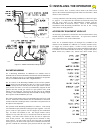
# NAME
DESCRIPTION
12 OPEN EDGE
Momentary or continuous signal.
This input is active only when referenced to the opening
direction, it has no effect on the gate when closing or about to
close. If activated when the gate is opening the gate will
stop, pause and reverse in the close direction for 1/2 second
(approx. 2 inches) and stop. Continuous activation will
prevent the gate from moving in the open direction. If a
second activation occurs before the limit switch is activated
the gate will stop and a require a renewed, intended input to
move in the open direction and before an automatic
activation device (timer, etc.) will operate. This input is
intended for Electric Gate Edge systems and other minimum-
contact devices as appropriate. Connect here and to
terminal #16 COMMON. Multiple devices may be connected
in parallel.
13 CLOSE EDGE
Momentary or continuous signal.
This input is active only when referenced to the closing
direction, it has no effect on the gate when opening or about
to open. If activated when the gate is closing the gate will
stop, pause and reverse in the open direction for 1/2 second
(approx. 2 inches) and stop. Continuous activation will
prevent the gate from moving in the close direction.
Continuous activation while the gate is open will prevent the
Timer-To-Close function (if enabled) from automatically
closing the gate. If a second activation occurs before the
limit switch is activated the gate will stop and a require a
renewed, intended input to move in the close direction and
before an automatic activation device (timer, etc.) will
operate. This input is intended for Electric Gate Edge
systems and other minimum-contact devices as appropriate.
Connect here and to terminal #16 COMMON. Multiple
devices may be connected in parallel.
14 MASTER OPEN
Momentary or continuous signal. Master
(output configuration)
This terminal is used to coordinate two independent systems
(two control box/mechanical unit combinations controlling
separate gate leaves). Connects to terminal #6 (OPEN) in
the companion control box and controls the direction of
movement in the companion box (Switch S3 ON).
15 MASTER CLOSE
Momentary or continuous signal. Master
(output configuration)
16 COMMON
Common connection for low voltage
signal inputs, terminals 3 through 15.
17 CLOSE LIMIT
SWITCH
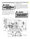
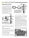
Connection for Limit Switch Input — See
page 13, Fig. 13 or page 14, Fig. 15, for
Limit Switch Wiring (single or bi-parting)
This terminal is used to coordinate two independent systems
(two control box/mechanical unit combinations controlling
separate gate leaves). Connects to terminal #7 (CLOSE) in
the companion control box and controls the direction of
movement in the companion box (Switch S3 ON).
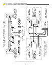
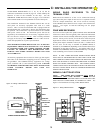
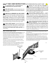
TERMINAL STRIP REFERENCE CHART
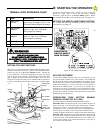
C: INSTALLING THE OPERATOR