


11
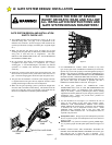
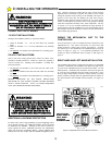
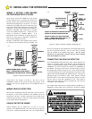
INSTALLING THE GS4000 CONTROL BOX
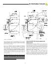
The GS4000 CONTROL BOX may be mounted remotely from
the MECHANICAL UNIT. Two mounting holes are provided
on each flange of the CONTROL BOX (four total). These
should be used to mount the CONTROL BOX to a solid, flat
surface. The CONTROL BOX should be located so that the
Gate and the MECHANICAL UNIT/UNITS ARE IN FULL
VIEW FROM THE CONTROL BOX.
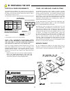
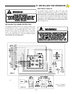
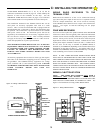
ELECTRICAL HOOK UP
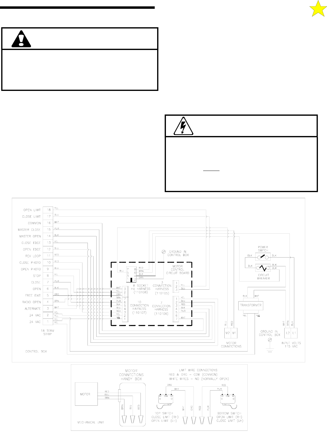
The GS4000 electrical connection is made at the Input Volts
terminals in the CONTROL BOX, see Figure 11. You will need to
drill holes as required on the bottom of the CONTROL BOX to
permit conduit entry. Run a flexible water tight conduit from the
service junction box to the GS4000 CONTROL BOX. Pull three #14
wires from the service junction box in this conduit to the GS4000
Control Box. If the GS4000 is wired for 115 Volts, pull a black,
white and green wire. If the GS4000 is wired for 230 Volts, pull a
black, red and green wire.
TO AVOID ELECTRICAL DAMAGE TO OPERATOR
DO NOT ALLOW TOTAL WIRE LENGTH FROM
THE CONTROL BOX TO AC POWER SERVICE
PANEL
PLUS
THE DISTANCE FROM THE
CONTROL BOX TO THE MECHANICAL UNIT TO
EXCEED WIRE LENGTH GIVEN IN TABLE 1 FOR
WARNING!
WARNING!
RISK OF ENTRAPMENT.
TO MINIMIZE POTENTIAL FOR GATE CONTROLS
TO BE ACTIVATED WHILE ALREADY IN USE,
LOCATE THE GS4000 CONTROL BOX IN FULL
VIEW OF THE GATE.
Figure 11: Schematic
& Wiring Diagram
110104
C: INSTALLING THE OPERATOR