


13
C: INSTALLING THE OPERATOR
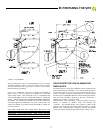
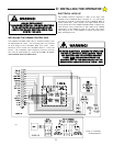
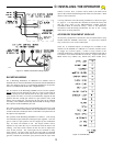
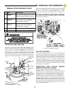
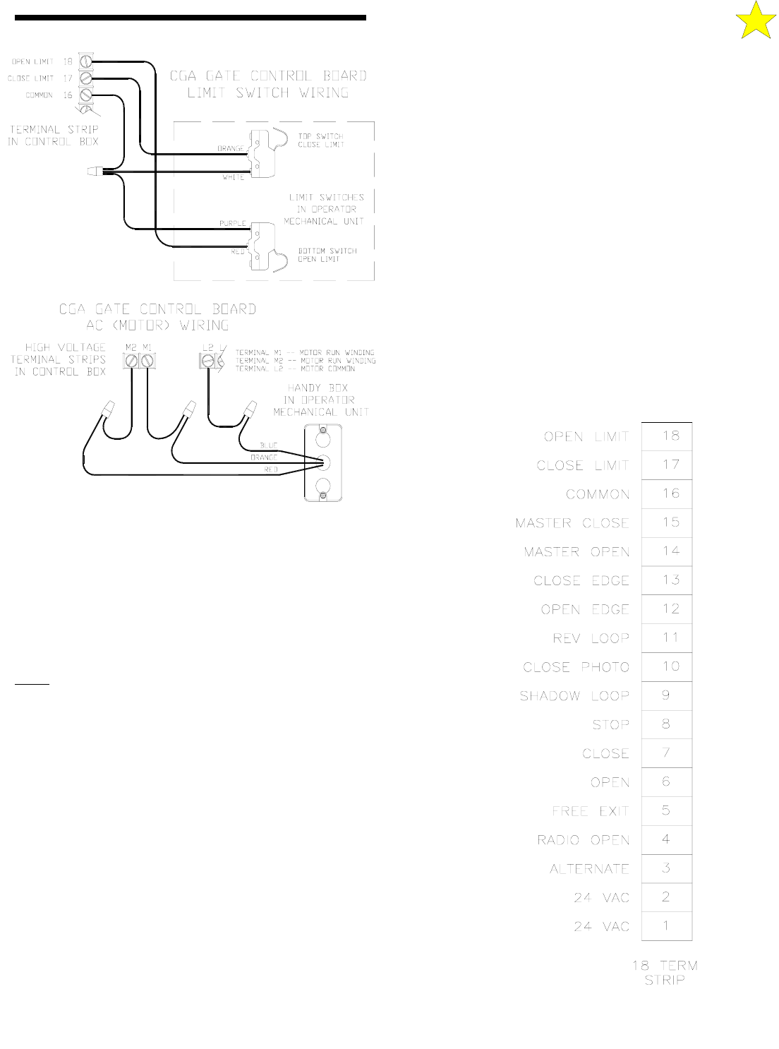
Figure 13: GS4000 Limit & Motor Wiring Diagram
110093
contact is closed. Now, a contact will be made to the limit switch
input at the terminal board through both limit switch contacts. Both
motors will be turned off.
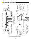
A wiring schematic of the Bi-Parting installation is shown in Figure
15, page 14. It is important this schematic be followed closely and
that the color codes at the MECHANICAL UNITS and the
CONTROL BOX be followed exactly. Most of the difficulties
encountered with Bi-Parting installations are due to the wiring
instructions not being followed.
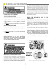
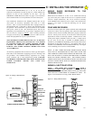
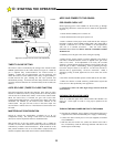
ACCESSORY EQUIPMENT HOOK-UP
All accessory equipment is connected to the 18 terminal barrier strip
located inside the GS4000 Control Box. To expose this terminal
strip, remove the cover on the Control Box.
There are 13 command inputs (#3 through #15) available to the
installer on the GS4000 in a addition to a common terminal (#16).
To trigger any of these inputs, a switch or relay closure to the
common terminal for a duration longer than 100 milliseconds and of
a resistance of less than 100 ohms is necessary. Eight of the inputs,
FREE EXIT (#5), OPEN (#6), STOP (#8), REV LOOP (#11),
BI-PARTING WIRING
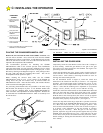
For a Bi-Parting installation, an additional two conduits must be
installed between the First Mechanical Unit and the Second Mechanical
Unit. (See Figure 8, page 8.) For a Bi-Parting installation, one operator
must be a Left Hand unit and the other a Right Hand unit.
The two motors of the Bi-Parting GS4000's will be wired in parallel.
BOTH
motors will run until both are shut off. If the two gate leafs do
not open exactly the same amount, then the first gate leaf to reach it's
open position will have to be held (or mechanically stopped) in that
position until the second gate reaches its open position. Now, both
motors can be turned off. The stop for the first gate can be installed
externally or the GS4000 internal Stop Pall mounted on the large output
drive sprocket of the GS4000 may be used.
The Limit Switch contacts of the two Bi-Parting units need to be wired
in series. Both limit switch contacts must be closed before a connection
is made to the limit switch input at the Control Box to stop the motors at
the Open or Closed position.
The operation of the Bi-Parting installation is as follows: After receipt
of a command to open, both units will begin to open together. The first
gate to reach its open position will be stopped by the mechanical
stop. Its motor will continue to run. The Torque Limiter will be
adjusted to slip when the stop is encountered with the motor still
running. The limit switch contact on this first unit is adjusted to
close at this position. The second gate has not reached its fully
open position. Its limit switch will be still open and no command
will be given to the limit switch input at the terminal board until the
gate has reached the maximum open position and the open limit
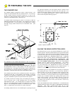
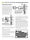
Figure 14: Terminal Strip