


4
TO REDUCE THE RISK OF SEVERE
INJURY OR DEATH: READ AND FOLLOW
ALL INSTALLATION INSTRUCTIONS AND
GATE SYSTEM DESIGN PARAMETERS!
WARNING!
GATE SYSTEM DESIGN AND INSTALLATION
SAFETY CHECK LIST:
• The GS4000 operator may be installed on a Class I, II, III, or IV
Vehicular Swing Gate. See page 3 for an explanation of the
different Class locations. See the last page of this manual for the
operator specifications (voltage, maximum gate weight & length
etc.).
• Make sure that the gate moves freely, all hinges are in good
working order, the gate does not bind in any manner and the gate
swing area is clean and free of irregularities. DO NOT
INSTALL THE OPERATOR UNTIL ALL GATE PROBLEMS
HAVE BEEN CORRECTED.
• Do not increase the built-in overload detector adjustment or
overtighten the torque limiter to compensate for a poorly
working gate. A well maintained gate will ensure easy manual
operation (if needed) and maximum operator obstruction
sensitivity.
• Install the operator on the inside of the property/fence line. DO
NOT install an operator on the public side of the fence line or
gate. Outward swinging gates should not open into public areas.
• The gate must be installed in a location so that enough clearance
is supplied between the gate and any adjacent structures when
opening and closing to reduce the risk of entrapment.
• Make sure the gate operating system is placed far enough back
from the road to eliminate traffic backup. The distance from the
road, size of the gate, usage level and gate cycle/speed must be
taken into consideration to eliminate potential hazards.
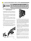
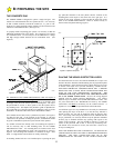
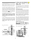
• For ORNAMENTAL “GRILL TYPE” GATES (or any other
type of open gate where a handhold or toehold may be achieved),
injuries may occur when people put arms through the openings or
children “ride” the gate by standing on the bars and holding on to
the gate. THIS POTENTIAL HAZARD CAN BE MINIMIZED
BY INSTALLING A MESH SCREEN ON THE GATE. Allstar
strongly recommends the entire gate and adjacent fence area the
gate covers when open be meshed or guarded such that a
handhold or toehold cannot be achieved. See Figure 2.
• All Allstar gate operators are VEHICULAR GATE
OPERATORS and as such are NOT RECOMMENDED FOR
PEDESTRIAN traffic. In installations where pedestrians are
likely to be nearby, install a pedestrian gate and use leading
edge detectors and/or photocells in your design to protect system
entrapment zones. Allstar can provide these products for
incorporation in your design.
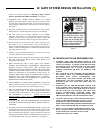
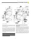
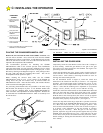
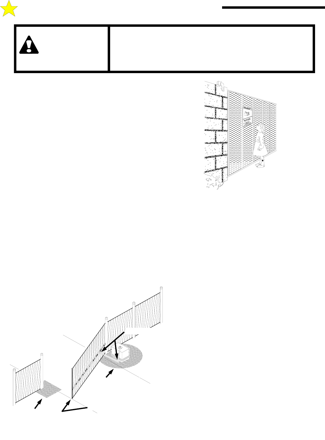
• Use the illustration at left (Figure 3) to minimize the risk of
injury in your design of the swing gate operator system.
IDENTIFY THE ENTRAPMENT ZONES AND PINCH
POINT AREAS IN YOUR GATE. Design the gate installation
to minimize the risk of entrapment in these areas. Install
additional safety equipment such as four wire edges and
photocells to further minimize risk. All entrapment zones are
required to be protected.
• Entrapment Zones: Design in personal entrapment protection
devices to protect people from entrapment in the zones shown in
Figure 3 at left.
• Pinch Points: Use protective measures (guards, padded edges,
etc.) to protect people from the pinch points shown in Figure 3 at
left.
• SWING GATES HAVE THE POTENTIAL HAZARD OF
HANDS AND FINGERS BEING PINCHED between the gate
edge and the post to which the gate is mounted. It is
recommended that the hinges be mounted so that this opening
Figure 2
104949
A: GATE SYSTEM DESIGN/ INSTALLATION
PINCH POINTS
ELECTRIC GATE EDGE
ENTRAPMENT
ZONE
ENTRAPMENT
ZONE
104932
Figure 3