


8
ELECTRICAL POWER REQUIREMENTS
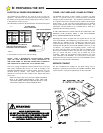
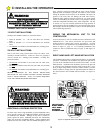
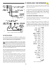
The GS4000 can be ordered for 115 Volts AC (VAC) or 230 VAC
operation. The AWG wire size for the electrical service depends on
the distance of the operator from the breaker panel. Refer to Table 1
to determine the correct wire size.
The DISTANCE column is the ideal distance from the breaker panel
to the operator for a given wire size and voltage.
NOTE! FOR A BI-PARTING INSTALLATION, THERE
WILL BE TWO MECHANICAL UNITS OPERATING AT
THE SAME TIME. IT WILL BE NECESSARY TO REDUCE
THE LENGTHS IN TABLE 1 BY A FACTOR OF TWO.
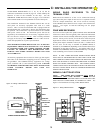
Class 2 low voltage wiring from external controls such as a key pad,
card reader, telephone entry device, etc. must be brought to the
GS4000 CONTROL BOX by a separate conduit from the 115 VAC
electrical hook up conduit. Low voltage control wires MUST
NEVER be routed in the same conduit as the HIGH VOLTAGE
power wires.
Note! The limit switch wires from the GS4000 CONTROL
BOX to the GS4000 MECHANICAL UNIT ARE LOW
VOLTAGE WIRES AND MUST BE ROUTED IN A LOW
VOLTAGE CONDUIT TO THE CONTROL BOX.
OTHER VOLTAGES AND 3 PHASE SYSTEMS.
The GS4000 can operate at other voltages or on three (3) phase
systems. To operate at 440 VAC it will be necessary to install an
external step down transformer. The transformer should be located
in a separate electrical box and protected by suitable circuit breaker
and/or fusing. A 440 Volt rated switch should also be installed.
Follow local electrical codes or the National Electrical Code. The
transformer selected should be UL LISTED and be rated for a
minimum 700 Volt-Amperes (Watts).
IF TWO MECHANICAL UNITS ARE TO BE USED FOR A BI-
PARTING GATE SYSTEM, THEN A 1000 VOLT-AMPERE/
WATT TRANSFORMER MUST BE USED.
Operating from a three (3) phase line will require the use of a 230
VAC rated GS4000. The GS4000 may be operated from a 230 Volt
"Delta" line or a 120/208 "Y" line. In either case, ONLY one "leg"
of the three phase line will be used. The unbalance of the line will be
minimal since the full rate current of the GS4000 at 220 VAC is only
2.2 amperes. (4.4 Amperes for a bi-parting system.) Connect any
two wires of the three phase system to the 230 VAC GS4000 Tape
the third wire carefully so that it does not short to any other object.
(The "Y" system will have 4 wires, one of which will be the
"common". Make sure the common is NOT selected as one of the
wires connected to the GS4000.) It is always best to also pull a
ground wire from the electrical service box to the GS4000 to ensure
the frame is securely affixed to GROUND.
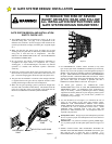
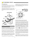
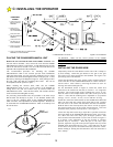
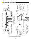
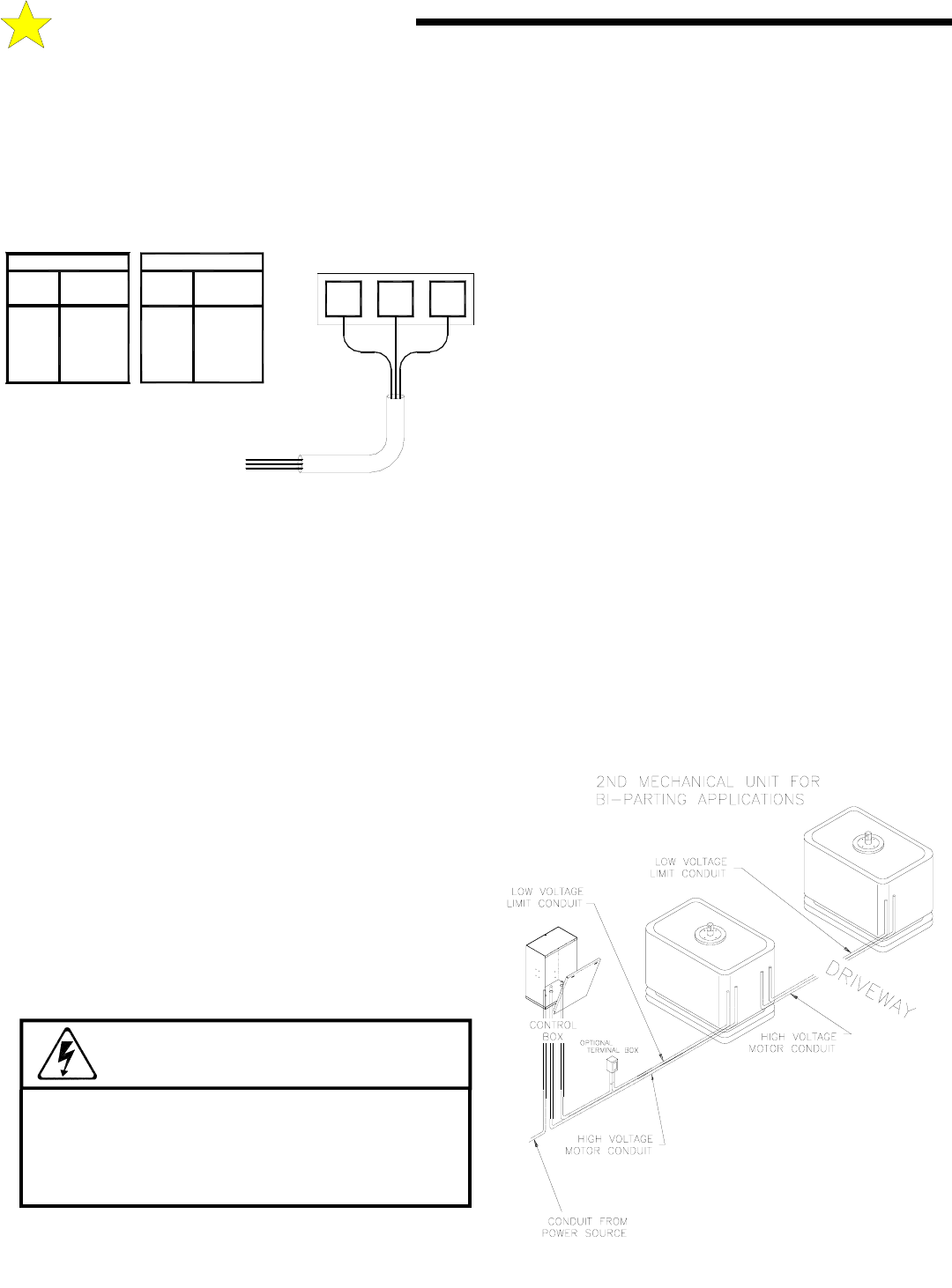
SERVICE CONDUIT
For new installations the conduit for the High Voltage may be
brought to a junction box near where the GS4000 CONTROL BOX
will be located or it may be brought directly to the Control Box.
WARNING!
AVOID ELECTROCUTION:
DO NOT ROUTE LOW VOLTAGE WIRES IN SAME
CONDUIT AS HIGH VOLTAGE WIRES. FOLLOW
ALL LOCAL ELECTRICAL CODES OR THE
NATIONAL ELECTRICAL CODE.
104952
Figure 8: Service Conduits
B: PREPARING THE SITE
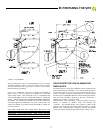
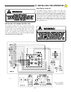
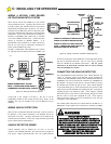
AC POWER SOURCE
TYPICAL CONNECTIONS
50 FT
#14
100 FT
#14
NOTE: DISTANCE IS TOTAL LENGTH OF
WIRE FROM CIRCUIT BREAKER IN THE
MAIN PANEL TO THE GATE OPERATOR.
600 FT
400 FT
250 FT
150 FT
#6
#10
#8
#12
#6
#10
#8
#12
300 FT
75 FT
125 FT
200 FT
DISTANCE
WIRE
SINGLE GATE
SIZE
DOUBLE GATE
WIRE
SIZE DISTANCE
120 VAC, 15A
Dedicated Circuit
HIGH VOLTAGE TERMINALS
GND
L2 L1
Table 1
110112