


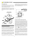
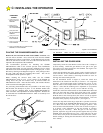
10
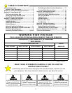
HARDWARE
LEGEND
1
(1 EA) 1/2-13 X 2”
BOLT & 1/2 FLAT
WASHER
2
(2 EA) 1/2-13
NYLOCK NUT &
1/2” FLATWASHER
3
(2 EA) 5/16-18 X
5/8L SQ HEAD SET
SCREWS
4
(1 EA) 1/2-13 X 2-
3/4” BOLT & 1/2
FLAT WASHER
5
(2 EA) 1/4 -20 X 1-1/2” BOLT & 1/4
FLAT WASHER
6
(2 EA) 1/4-20 HEX NUT, INT TOOTH LOCK
WASHER, 1/4 FLAT WASHER
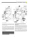
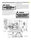
PLACING THE GS4000 MECHANICAL UNIT
Remove the rain seal from the shaft of the GS4000. SAVE IT! The
rain seal will be used later. Next, remove the cover from the GS4000
MECHANICAL UNIT by removing the 1/4 inch diameter bolts on each
side of the Unit and set it aside. It is one of the last items that will be
replaced at the completion of the installation.
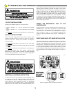
The recommended procedure for attaching the GS4000
MECHANICAL UNIT to the concrete pad (for those installations
where the anchor bolts were not previously installed) is first to locate
and drill the hole for the mounting hole nearest to the gate post. Locate
this hole by referring to the diagram in Figure 6. After placing a bolt in
the hole, mark and drill the remaining three holes. This can be
accomplished with the operator in place.
Before inserting the concrete bolts, make sure the GS4000
MECHANICAL UNIT is level. If any corners of the GS4000 are
resting above the pad, flat washers may be inserted under the
MECHANICAL UNIT. Place the flat washers, lock washers and nuts
on the concrete bolts and tighten securely.
For previously placed anchor bolts, the procedure is the same except
that the bolts will already be in place. If 1/2" diameter anchor bolts
were set, the 3/4" mounting holes on the GS4000 MECHANICAL
UNIT will allow some adjustment for desired alignment. Washers can
be used under the GS4000 MECHANICAL UNIT to accurately level
the unit as above.
TO REVIEW: Make sure the correct position of the GS4000
MECHANICAL UNIT from the center line of the gate hinge pivot
point to the center line of the GS4000 is in accordance with the drawing
of Figure 6.
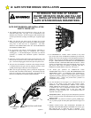
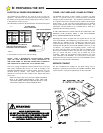
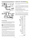
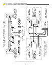
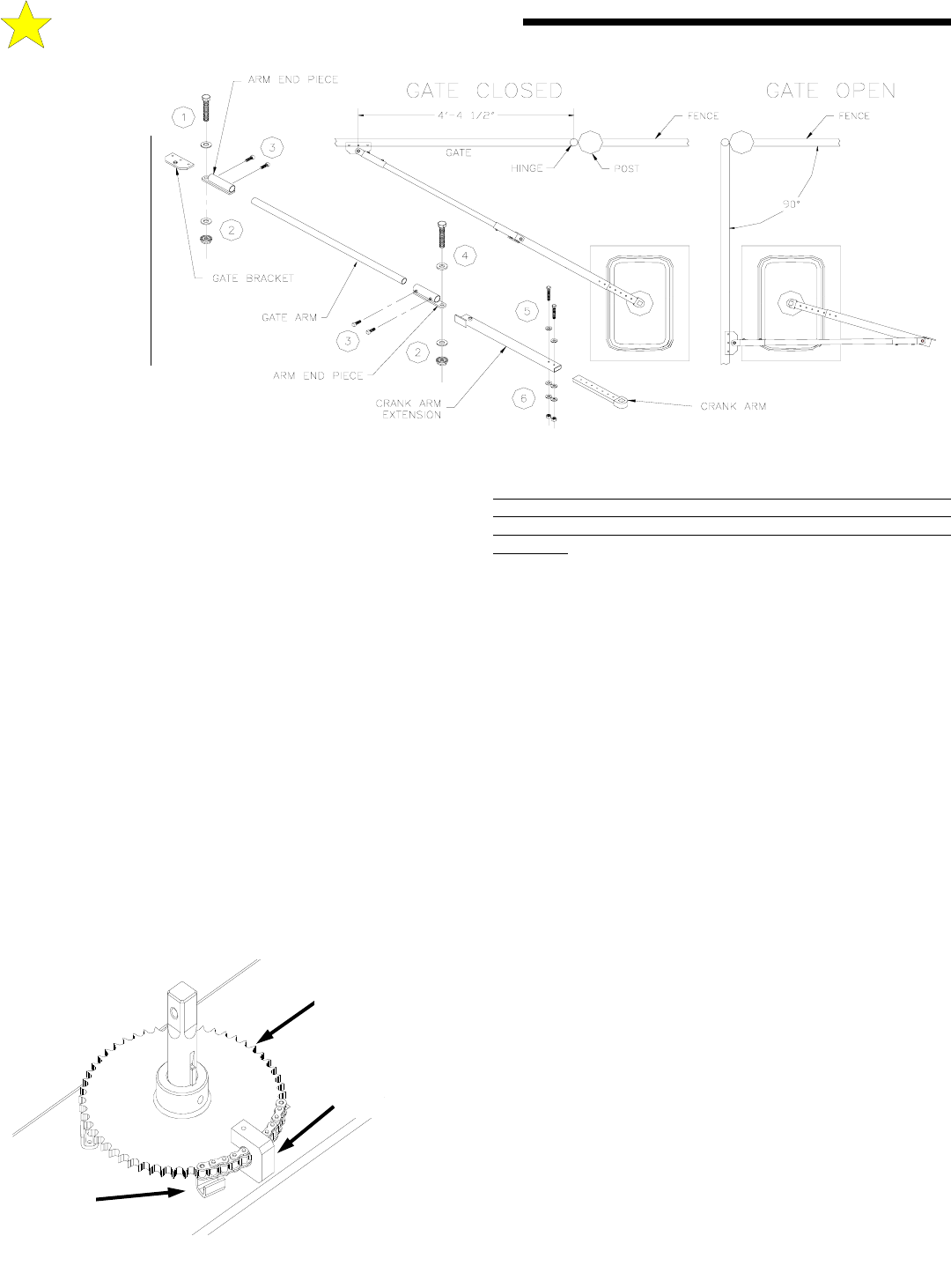
INSTALLING THE GS4000 ARM
Temporarily locate the Gate Bracket on the Gate with C-clamps or
by tack welding. Install the gate bracket to the gate so the gate
arm will be level when connected to the GS4000. See Figure 9 for
positioning of the Gate Bracket.
Loosen the adjustment nut of the Torque Limiter located on the top
of the Gear Box on the GS4000 MECHANICAL UNIT with the 1-
5/8 hex socket. This is done by removing the small set screw on
the large nut and loosening the nut.
For the installation shown in Figure 9, attach the Crank Arm
Extension to the Crank Arm with the (2) 1/4-20 x 1-1/2” long bolts
provided. The overall length of the cranking arm is now 33 5/8”
from the center of the Output Shaft to the center of the pivot at the
“elbow.” Note that the cranking arm is adjustable to (5) possible
settings: 32-1/8”, 30-5/8”, 29-1/8”, 27-5/8” and 26-1/8” long.
Install the Crank Arm and Extension on the GS4000 main shaft and
make sure the Crank Arm swings freely from side to side. Connect
the Gate Arm to the Crank Arm Extension and the Gate Bracket.
With the Gate in the closed position, the "elbow" will be up against
the closed position stop on the Crank Arm Extension. The Gate
should be in the properly closed position. (See Figure 9.)
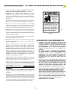
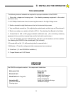
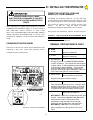
Loosen the Stop Pall on the large output drive sprocket located on
the output shaft on the GS4000 MECHANICAL UNIT. (See Figure
10.) Move the Gate to the fully open, 90 degree position. The
Arm extension should fold back over the arm as shown in Figure 9.
If it doesn't, some adjustment of the gate bracket or operator
position may be necessary. With the gate in the fully open
position, adjust the stop pall on the sprocket against the stop on the
GS4000 frame and tighten the set screw. Open and close the gate
several times until you are satisfied that the arm position is correct.
Finish welding or bolting the Gate Bracket to the Gate and remove
the C-clamps.
** HARDWARE NOT TO SCALE **
C: INSTALLING THE OPERATOR
Figure 9: Arm Positions
104961
DRIVE
SPROCKET
STOP PALL
Figure 10: Stop Pall
STOP
106318