


6
THE CONCRETE PAD
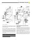
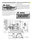
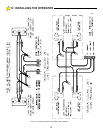
The standard GS4000 is designed to operate a single leaf gate. The
control box and mechanical units are separate devices. It is necessary
to find a suitable location to mount the control box, i.e., post or wall.
Separate low voltage and high voltage conduits will be run between the
control box and mechanical unit. (See Figure 8.)
To properly install a bi-parting gate system, it is necessary to add one
additional mechanical unit to the design. The control box will operate
two mechanical units. It is necessary to run an additional low voltage
and high voltage conduit between the two mechanical units. (See
Figure 8.)
The Installation of the GS4000 MECHANICAL UNIT will require a
suitable concrete pad as a mounting base. The dimensions of the
concrete pad should be sufficient to allow at least 3" of clearance from
each edge of the pad to the nearest operator mounting hole. The top of
the pad should be at least 3" above grade to raise the operator above
any standing water. The depth of the pad below grade is dependent on
the weight and size of the gate and the soil conditions at the site of the
installation. ALWAYS FOLLOW LOCAL BUILDING CODES.
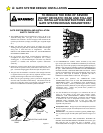
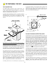
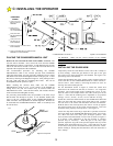
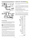
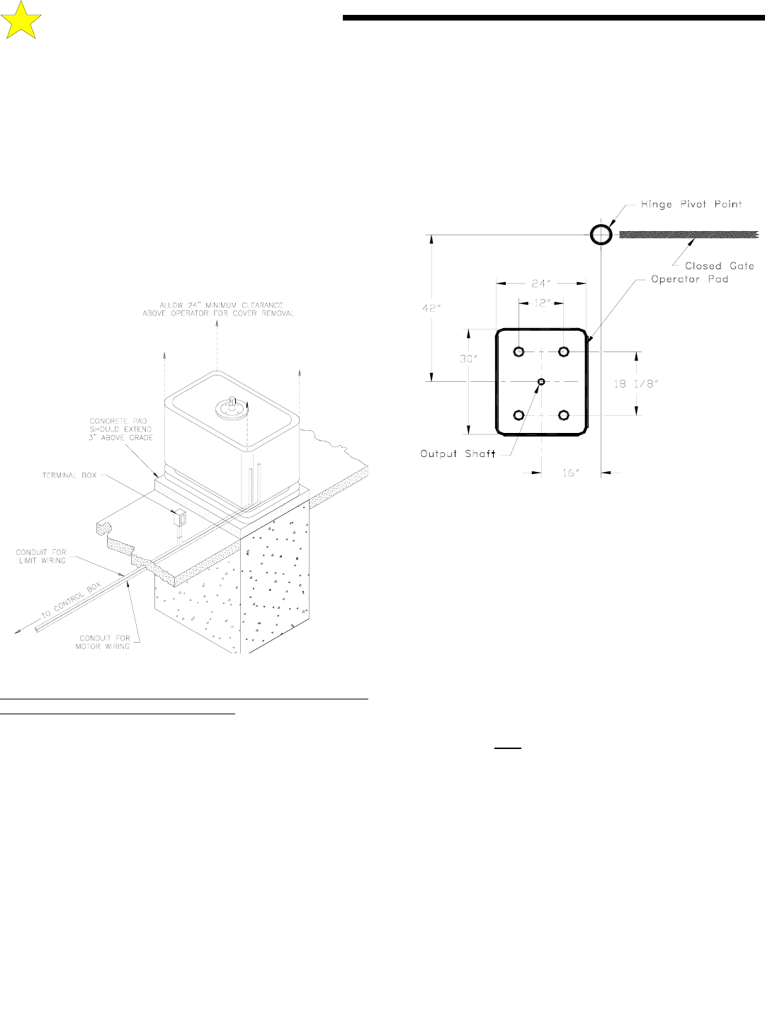
If no suitable concrete base exists, a pad must be poured. See Figure 6
for plans for this pad. If the location of the operator is such that
vehicles have the potential of hitting the operator, consideration should
be given to installation of protective posts in front of the operator.
If a suitable concrete base already exists for mounting the operator it
will be necessary only to drill mounting holes for the GS4000
MECHANICAL UNIT. 3/4" mounting holes are located on the front
and rear of the MECHANICAL UNIT. The bolt pattern is shown in
Figure 6. The mounting bolts should be 1/2" diameter or larger. "Red
head" or wedge anchor concrete bolts are usually satisfactory.
If mounting anchor bolts are to be installed prior to pouring the pad,
pay particular attention to the bolt pattern and the location of the
mounting holes with respect to the center line of the gate post. It is
critical for the proper operation of the Arm that the center line of the
shaft of the GS4000 MECHANICAL UNIT be located exactly as
shown on the bolt pattern drawing, Figure 6.
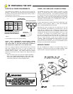
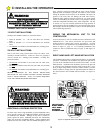
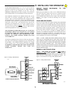
PLACING THE VEHICLE DETECTOR LOOPS
If Vehicle Detectors are to be used with the GS4000, the "Loops" to be
buried in the drive should be installed during the site preparation phase
of the installation. Proper placement of the Vehicle Detector wire loops
is critical if the loops are to provide satisfactory, extended service.
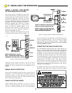
THE MOST IMPORTANT CONSIDERATIONS ARE: 1) PROPER
WIRE TYPE AND, 2) GOOD, TIGHT CONNECTIONS FROM THE
LOOP TO THE LOOP TERMINATING CONNECTOR. The
termination of the loop wires will be at the Vehicle Detector itself,
not on the GS4000 terminal board. Observe the wiring diagram
supplied with the Vehicle Detector Manufacturer. The Vehicle
Detector may be mounted in the GS4000 MECHANICAL UNIT. The
AC power delivered to the MECHANICAL UNIT by the GS4000
Control Box will NOT
be satisfactory for the Vehicle Detector. A
separate A/C service must be provided for the Vehicle Detector.
Two different types of Loop Installations will usually be encountered
when placing the loops in the drive: 1) If the driveway material is
already in place. saw cuts will be needed in which to place the loop
wire. 2) For loops where the paving material will be installed after the
loop is positioned, it is necessary that the loops be placed in Schedule
40 PVC pipe to maintain uniform loop spacing with respect to the
surface of the pavement. The loop should be placed 1.5" below the
surface of the pavement and at least 2" above any reinforcing steel.
The lead-in wires need not be in PVC, but must have a least six (6)
twists per running foot.
THE LOOP WIRES MUST BE CONTINUOUS. NO SPLICES OR
CONNECTIONS IN THE LOOP ARE TO BE PERMITTED BELOW
GROUND. THE ONLY CONNECTION WILL BE AT THE
TERMINATION OF THE WIRE AT THE VEHICLE DETECTOR.
Figure 6: Operator Footprint
104947
Figure 5: Pad Configuration
104951
B: PREPARING THE SITE