


25
ALL APPROPRIATE SAFETY FEATURES MUST BE
INCORPORATED INTO YOUR GATE SYSTEM.
KEEP GATE IN SIGHT: Never activate the gate unless it is in
sight. Install mounted controls in full view of the gate. Be sure the
gate area is clear before activating the gate, and watch the gate and gate area
as the gate is in motion.
LOCATE MANUAL CONTROLS SAFELY: A manual
control such as a pushbutton or keyswitch must be included in
your gate system design to be used if automatic controls such as radio
controls or loop detectors do not function. Carefully consider the placement
of the manual control: It must be out of reach of the gate so that no one
pushing the button or inserting the card is in the path of the gate or moving
parts; it must also be within sight of the gate so that the operator can watch
the gate and gate area during operation. The recommended minimum
distance between the gate or fence and manual controls accessory is 10
INSTALL SAFETY DEVICES: In residential applications or in
areas where pedestrians may be present, or if your gate closes
automatically, be sure an electric edge(s) and/or a photoelectric sensor(s)
has (have) been installed and is/are operating properly. These features are
intended to detect pedestrian traffic and prevent injury or entrapment.
Loop detectors may be installed to detect vehicular traffic and prevent
vehicular damage.
MAINTAIN THE GATE AND GATE HARDWARE: A
damaged gate or one that cannot be easily opened and closed
manually must be repaired before installing a gate operator. A poorly
operating gate may cause the load sensing device of the operator to fail,
causing a risk of entrapment. Never overtighten the clutch or load sensing
device to compensate for a poorly swinging gate. Correct all mechanical
problems on the gate and gate hardware before installing the gate operator.
Have a qualified service technician make repairs to the gate.
MAINTAIN ALL COMPONENTS OF GATE SYSTEM:
Follow the maintenance instructions included with the gate, the
gate operator, and the safety features and/or accessories that make up your
gate operator system. Have a professional service technician perform any
adjustments or maintenance to the components. Fully test all safety
features monthly. Discontinue the use of faulty safety equipment
immediately, and have the equipment serviced or replaced. by a qualified
service technician. The gate must reverse on contact with a solid, rigid
object or when an object activates the non-contact sensors. After adjusting
the force or limits of travel, retest the gate operator. Failure to adjust and
retest the gate operator properly can increase the risk of injury or death.
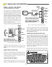
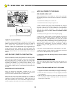
KNOW YOUR GATE ARM DISCONNECT FEATURE FOR
MANUAL OPERATION: In the event of a power outage, you
may need to manually operate your gate. The GS4000 is equipped
with a keyed padlock to permit the gate arm to be manually disconnected
from the GS4000 operator. This will allow you to manually push the gate
open or close as needed. Be sure to have the service technician or dealer
installing your gate system give you the key to the padlock and show you
how to use this feature quickly and safely. Keep the key in a safe,
accessible place. Manual operation is to be attempted only when the
operator is not moving the gate under power.
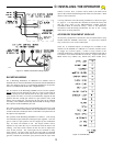
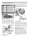
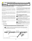
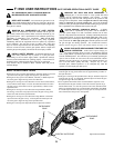
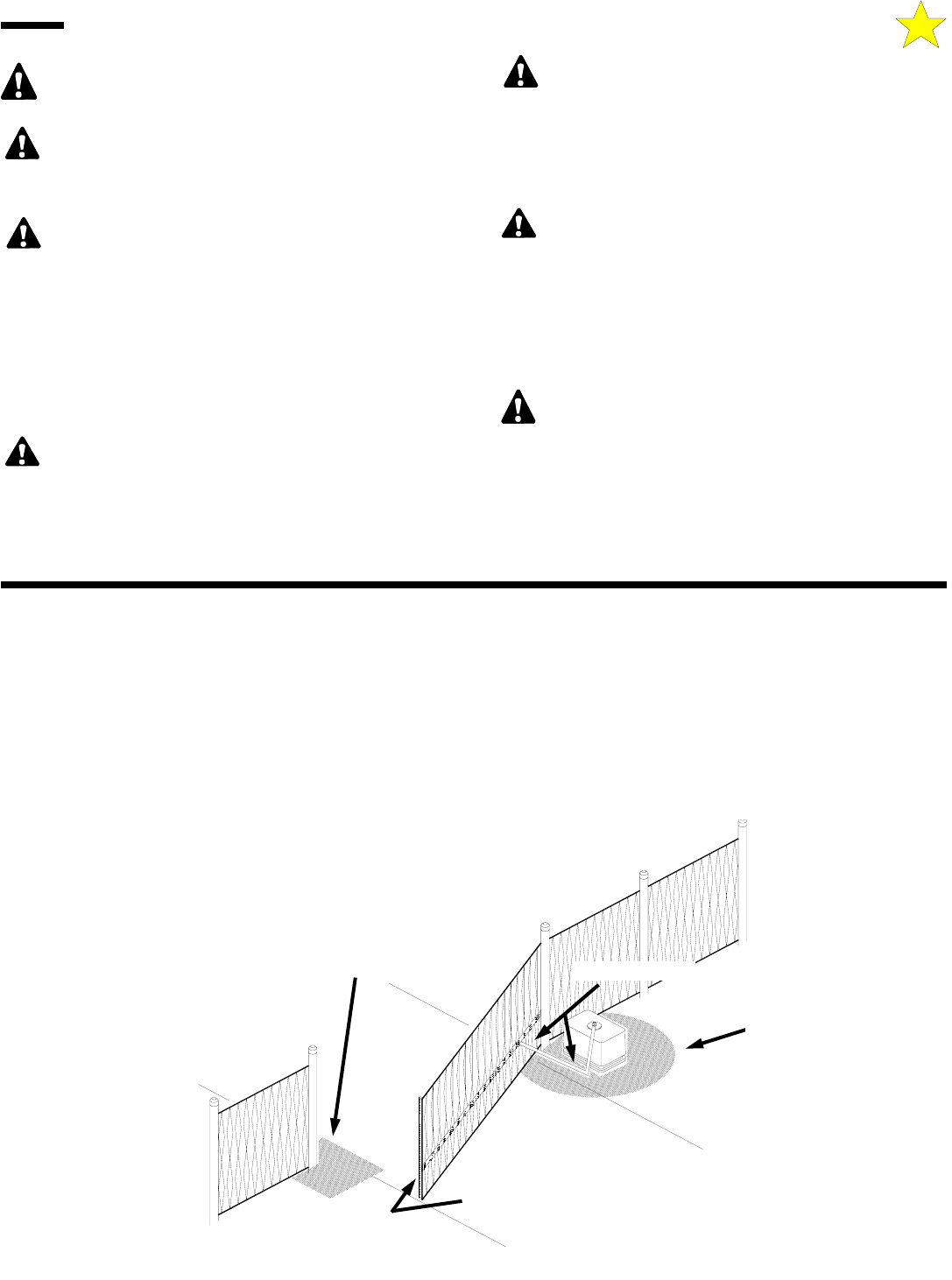
PINCH POINTS
ENTRAPMENT
ZONE
ELECTRIC GATE EDGE
ENTRAPMENT
ZONE
104932
Figure 26: Pinch Points
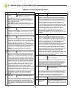
BASIC OPERATIONAL GUIDE
•If the gate is fully closed an Open Button, Alternate, Radio or Free Exit
input will cause the gate to begin moving in the open direction.
•If the gate is fully open a Close Button, Alternate, or Radio input will
cause the gate to begin moving in the close direction.
•If the gate is moving in a Close direction a Close Non-Contact Sensor,
Close Contact Sensor input or a Close Overload activation will cause
the gate to stop, pause and reverse for approximately 2 inches in the
Open direction.
•If the gate is moving in a Close direction an Open Button, Radio,
Reversing, or Free Exit Loop input will cause the gate to stop, pause
and reverse and run in the Open direction.
•If the gate is moving in a Close direction a Stop Button or Alternate
input will cause the gate to stop. A subsequent Alternate input will
cause the gate to begin moving in the Open direction.
•If the gate is moving in an Open direction an Open Non-Contact
Sensor, Open Contact Sensor input or an Open Overload activation will
cause the gate to stop, pause and reverse for approximately 2 inches in
the Open direction.
•If the gate is moving in an Open direction a Stop or Alternate input will
cause the gate to stop. A subsequent Alternate input will cause the gate
to begin moving in the Close direction.
•Two sequential activations of the Overload detector (Open or Close
direction) before the gate reaches a limit will cause the operator to go
into the alarm mode. To reset the operator remove the obstruction and
either use constant pressure on a control button connected to the OPEN
or CLOSE input and move the gate to a fully open or closed position or
turn off and restore the power to the operator.
F: END USER INSTRUCTIONS GATE OPENER OPERATION & SAFETY GUIDE