


23
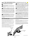
FINAL SETTING OF THE MOTOR OVERLOAD
SENSITIVITY
The motor overload sensitivity was preset for each direction before
turning on the main power to prevent the operator from "self-
tripping" during the preliminary adjustment period.
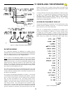
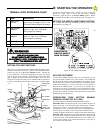
Adjust the Open Overload Force potentiometer, see Figure 20 fully
counter-clockwise then approximately 1/16 of a turn in the clockwise
direction. Start from the closed gate position and give the GS4000 an
open command and observe the Gate. If the gate stops and reverses
anywhere in the cycle turn the Open Overload potentiometer
approximately 1/16 in the clockwise direction. Repeat this process
until the gate will open without the Open Overload tripping and with
the Open Overload potentiometer in the most counterclockwise
direction. (Make sure the gate swings easily and there are no
obstructions in the path of the gate.)
Repeat the above adjustment procedure for the close direction.
CAUTION: During this process the alarm will sound if the overload
sensor is activated two sequential times before the gate reaches a
limit (open or close). To reset the alarm sensor use constant pressure
on a control button connected to the OPEN or CLOSE input and
move the gate to a fully open or closed position or turn off and
restore the power to the operator.
When you are satisfied that you have the best settings, test these
settings by striking the gate a sharp blow with the palm of your hand
in both the open and close direction. The OVERLOAD should
respond immediately to your blow. If the Torque Limiter slips before
the overload is detected, the Torque Limiter will need to be tightened.
The purpose of the Torque Limiter is to protect the mechanical
components of the GS4000 (primarily the Gear Box). The Torque
Limiter should be adjusted so that the OVERLOAD will be activated
before slippage occurs.
IMPORTANT ! THE OVERLOAD POTENTIOMETERS
MUST BE ADJUSTED TO THE MOST SENSITIVE
POSITION POSSIBLE WITHOUT CAUSING "SELF-
TRIPPING" DUE TO THE GATE'S INHERENT FRICTION
OR TO VARIATIONS IN THE GATE HINGE. TRY
ADJUSTING THE POTENTIOMETERS SEVERAL TIMES
BY SMALL INCREMENTS, TESTING THE OVERLOAD
BY STRIKING THE GATE WITH YOUR PALM IN BOTH
DIRECTIONS OF TRAVEL. REPEAT THIS TEST UNTIL
YOU ARE SATISFIED YOU HAVE THE MOST
SENSITIVE SETTING OF THE POTENTIOMETERS.
Disconnect the crank arm from the output shaft to permit re-
installation of the cover on the mechanical unit. Install the operator
cover and secure it to the frame with (2) 1/4-20 hex bolts. Remember
to re-install the rain seal on the output shaft. Re-connect the gate arm
on the GS4000 and secure it with the padlock provided. Complete
the installation by replacing the cover on the Control box.
Review the Installation Notes in Section A of this manual and
describe the gate system operation to the end user. Review the Gate
Operator System Operation and Safety Guide in Section F of this
manual with the end user.
You are now ready to install and connect the ancillary
equipment. INSTALLATION STEPS DETAILED IN
SECTIONS A, B, C AND D MUST BE COMPLETE
BEFORE PROCEEDING.
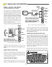
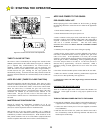
1. Installing Entry Devices
After you are satisfied that all the loops are functioning properly,
proceed with the installation of any additional entry devices, such as
a Radio Receiver, Telephone Entry or Key Pad. Connect the Radio
Receiver and observe the precautions regarding radio receivers
described on page 15. Other entry devices MUST be connected to
the appropriate terminal(s) as their functions warrant as described on
pages 17 through 19.
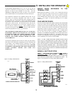
2. Installing a Magnetic Lock
The GS4000 can (as an option) be configured and wired to provide a
closed contact to control the power to a Magnetic Lock. This option
must be ordered at the same time as the operator or as a kit
installation after the original installation.
The magnetic lock must be powered by an external source, the
operator provides only a contact to energize and de-energize the lock.
Note: the Allstar GS1000 (slide gate operator) uses the same Control
Board as the GS4000, except for the configuration of the LOCK
circuitry. If the LOCK is energized when the gate is opening or
closing, a GS1000 Control Board has been accidentally installed in
your GS4000 operator. It must be replaced with a GS4000 BOARD.
The Magnetic Lock will be released by the GS4000 about 100
milliseconds prior to giving the gate an Open Command. This time
delay is to allow the magnetic field in the Magnetic Lock to decay
and release the Lock prior to starting the gate.
E: INSTALLATION NOTES FOR AUXILIARY EQUIPMENT