


17
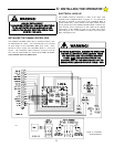
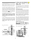
EXIT) and the RELAY COMMON signal connected to Terminal #16
(COMMON) of the GS4000, See Figure 19. DO NOT CONNECT
THE FREE EXIT OUTPUT SIGNAL TO ANY OTHER
TERMINAL, SUCH AS RADIO OPEN, BECAUSE THE GATE
WILL CLOSE AFTER REACHING THE OPEN LIMIT AND THE
TIMER TO CLOSE HAS COMPLETED ITS CYCLE, EVEN
THOUGH THE VEHICLE HAS NOT EXITED THE FREE OUT
LOOP.
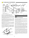
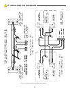
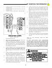
CONNECTING THE LOOP WIRES
Follow the instructions of the Vehicle Detector Manufacturer when
connecting the loop wires. Good, tight connections are most
important. It is recommended that these wires be soldered to the
wiring harness of the Vehicle Detector.
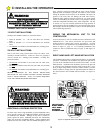
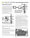
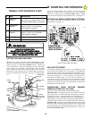
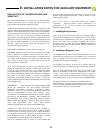
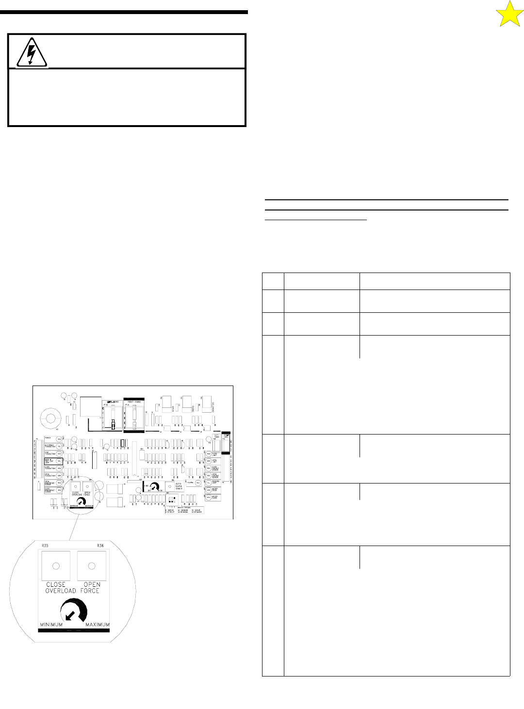
PRESETTING THE MOTOR OVERLOAD
SENSITIVITY POTENTIOMETERS
The GS4000 has independent adjustments for Open and Close
Overload Sensitivity. The GS4000 is shipped from the Factory with
the overload settings at their most sensitive setting. During the initial
check out phase, it will be necessary to adjust the sensitivity to
prevent inherent overloads from gate friction and other gate
anomalies. See Figure 20. Adjust the OPEN and CLOSE
OVERLOAD potentiometers approximately 1/4 turn clockwise.
Note! Turning the potentiometer clockwise decreases sensitivity.
Turning the potentiometer counterclockwise increases sensitivity.
WARNING: THE OVERLOAD POTENTIOMETERS MUST
BE SET MORE PRECISELY PRIOR TO COMPLETING THE
GS4000 INSTALLATION. (See, FINAL SETTING OF THE
MOTOR OVERLOAD SENSITIVITY)
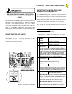
WARNING!
IMPROPER WIRING COULD CAUSE
ELECTROCUTION OR DAMAGE TO CIRCUITRY.
FOLLOW LOCAL BUILDING AND ELECTRICAL
CODES.
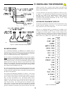
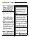
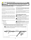
# NAME
DESCRIPTION
1 24 VAC
Provides maximum 10 VA auxiliary
power for accessories.
2 24 VAC
Provides maximum 10 VA auxiliary
power for accessories.
3 ALTERNATE
Momentary input, must be released
and re-entered to be recognized.
This input is used for “COMMAND OPEN/COMMAND
CLOSE” applications. The 1st signal will cause the gate
to begin opening. A 2nd signal received during the open
cycle will stop the gate immediately. A 3rd signal will
close the gate. Connect appropriate access control
devices to this terminal and #16 COMMON. Disable the
Close Timer (rotate pot fully counter-clockwise).
4 RADIO OPEN
Momentary input, must be released
and re-entered to be recognized.
Once activated the gate will open fully. Activation while
the gate is closing will cause it to re-open.
5 FREE EXIT
Momentary or continuous input.
Once activated the gate will open fully. Activation while
the gate is closing will cause it to re-open. Continuous
activation while the gate is open will prevent the Timer-
To-Close function from automatically closing the gate.
6 OPEN
Momentary or continuous signal. On/
Off mode set by Switch #1
WITH SWITCH 1 OFF: Once activated the gate will open
fully. Activation while the gate is closing will cause it to
re-open. Continuous activation while the gate is open
will prevent the Timer-To-Close function from
automatically closing the gate. Continuous signal
required to move the gate when in the alarm mode.
WITH SWITCH 1 ON: Gate does not respond to
pushbutton input when in the normal mode. Continuous
signal required to move the gate when in the alarm
mode.
TERMINAL STRIP REFERENCE CHART
C: INSTALLING THE OPERATOR
LOCATION OF
ADJUSTMENTS
OVERLOAD FORCE
Figure 20: Overload Force Adjustments
110125