


20
TIMER TO CLOSE SETTING
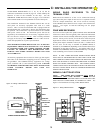
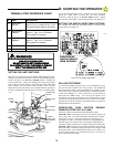
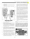
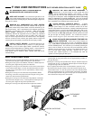
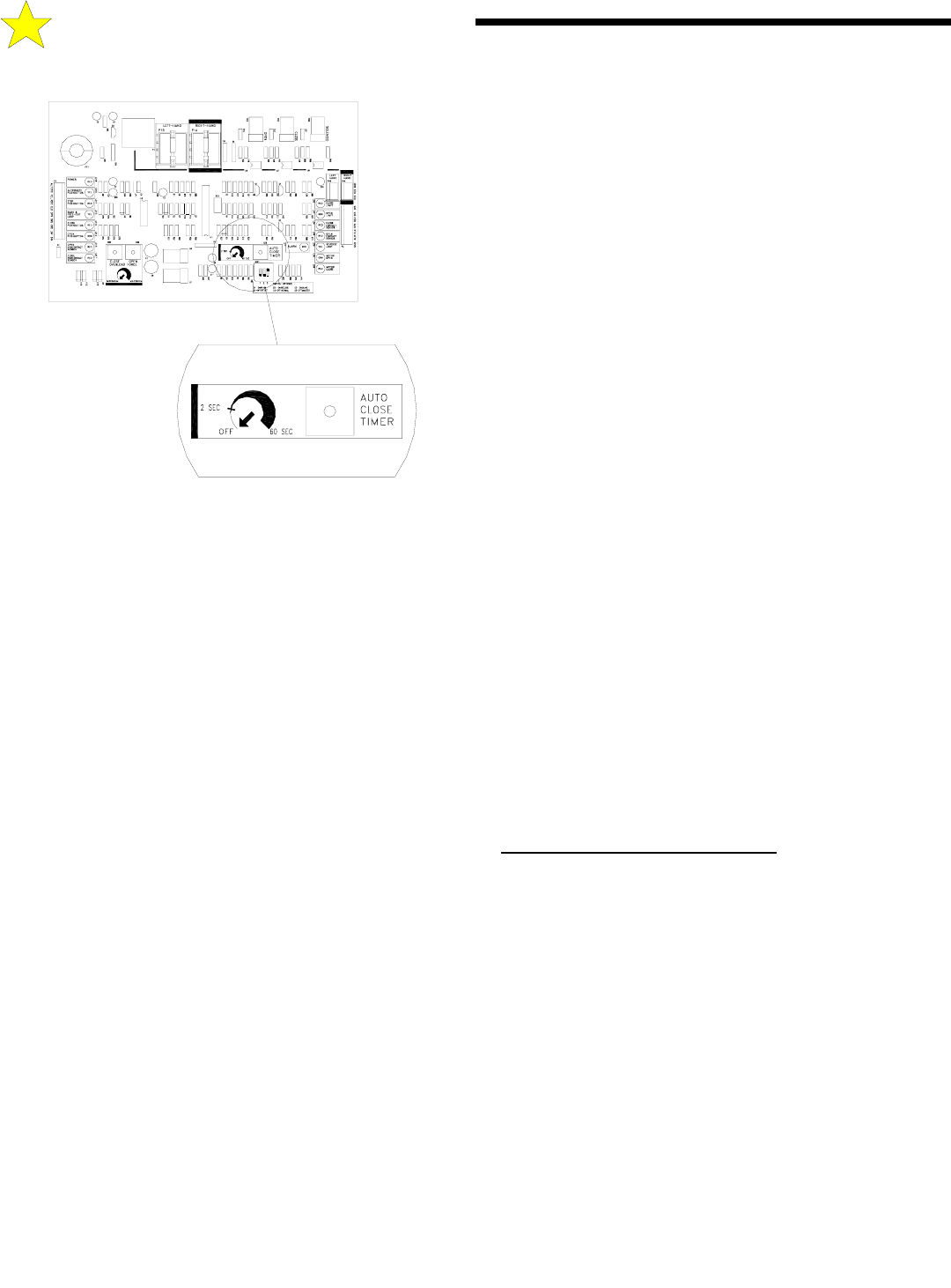
The Timer to Close is controlled by the setting of the “AUTO CLOSE
TIMER” potentiometer on the control board, see Figure 23. When the
pot is adjusted fully counter-clockwise the Timer-To-Close is
disabled. Turning the pot approximately 1/4 turn clockwise will
enable the Timer To Close function with a delay of approximately 2
seconds between the gate reaching the full open position and
automatically closing. To increase the time delay continue to turn the
pot in the clockwise direction to a maximum delay of 60 seconds (one
minute).
AUTO RE-CLOSE (TIMER-TO-CLOSE FUNCTION)
Switch S2 controls the Auto-Re-close function. If the Timer To Close
function is enabled (see above), setting Switch S2 to the ON position
will activate the Auto-Re-close feature on the motor control board.
When the auto-re-close is activated, the gate will re-close after
stopping and backing-off from a non-contact sensor input if the close
movement was initiated by the Timer-To-Close function on the
control board. The gate will not re-close if the sensor input was
received from a contact sensor or if the inherent overload sensor was
activated.
MASTER/SLAVE CONFIGURATION
Switch S3 controls the Master/Slave Terminals (#s 14 & 15)
configuration setting. The setting is used when two control boards
(boxes) are used in conjunction with two mechanical units.
With Switch S3 in the ON position terminals 6 & 7 (OPEN &
CLOSE) are in the Slave mode and could be coupled to and would be
controlled by a Master control board (box). With Switch S3 in the
OFF position terminals 14 & 15 are in the Master (output) mode and
could be coupled to and would control a Slave control board (box).
APPLYING POWER TO THE GS4000
PRE-POWER CHECK LIST
Before applying power to the GS4000 for the first time, go through
the following check list to ensure that all is in order for the application
of power.
1. Check that the GS4000 power switch is off.
2. Check that the breaker at the power panel is on.
3. With a voltmeter on the proper scale, check that the line voltage at
terminals L1 and L2 on the GS4000 control board is the voltage that is
expected. Connection of a 115 VAC GS4000 to an unexpected 230
VAC line is a common occurrence. This will cause readily
identifiable board failure that WILL NOT BE COVERED UNDER
WARRANTY.
4. Manually move the gate to the center of the gate opening.
5. Make sure the Torque Limiter is properly adjusted to slip under a
load when a moderate amount of force is applied to the gate in the
center of its travel. If the adjustment is too loose, the overload
sensitivity will not function properly and the Torque Limiter may slip
when the gate is under a wind loading. Start by tightening the large
nut on the Torque Limiter to 35 ft-lbs./in. To fine tune, increase or
decrease this by approximately 5 ft-lbs./in. increments. When a
satisfactory setting is found, tighten the set screw in the side of the
large nut.
6. Set all the Switch selectable options switches ON for the test mode.
7. Make sure that the overload sensitivity potentiometers (Open and
Close) are set to their preliminary start up position.
8. Temporarily remove the white high voltage connector from the
control board.
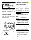
CHECKING THE INDICATOR LIGHTS
There are 16 indicator lights on the control board of the GS4000. See
Figure 24. These lights are used to verify proper operation of the
GS4000.
TURN ON THE MAIN POWER SWITCH TO THE GS4000.
• Note that the “POWER” lamp is lighted. This indicates that power
is applied to the control board and the power supply is functioning
1. Connect one end of a short piece of wire (not supplied) to terminal
#16 (COMMON).
2. With the other end of this wire, (make sure that this loose end is
free of insulation), touch the following terminals and observe the
noted response of the lamps.
D: STARTING THE OPERATOR
ADJUSTMENT
AUTOCLOSE TIMER
LOCATION OF
Figure 23: Location of Auto-Close Timer Adjustment
110125