


16
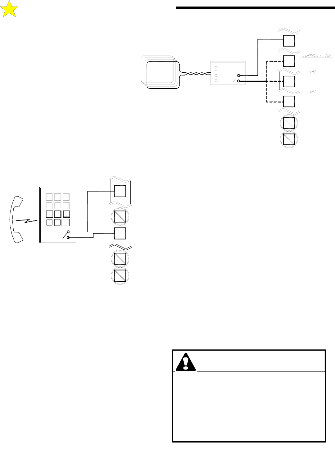
WIRING A KEYPAD, CARD READER
OR TELEPHONE ENTRY SYSTEM
These devices activate the GS4000 by a relay contact
closure within the device. Typically, these devices will
be used to open a gate with the Timer-To-Close feature
automatically closing the gate. In general, two wires or
terminals are provided by the device to operate the gate.
Follow the manufacturers instructions on locating these
connections. If one of the connections at the device is
labeled as COMMON, then connect this to Terminal
#16 of the GS4000 Terminal strip. Connect the other
contact to Terminal #5 (RADIO OPEN). If no
identification of the connections is noted at the device,
then the two wires may be connected to terminals #16
and #5 of the GS4000 in any order.
Keypads, Card Readers and Telephone Entry Systems
are typically located remotely from the GS4000. The
wiring used is low voltage or CLASS 2. Be sure to run an
independent conduit for this wiring from the Entry Device to the
GS4000. The wire size should be #16 or #18 stranded for ease of
handling.
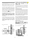
WIRING VEHICLE DETECTORS
There are three connections that need to be made; 1) the AC power to
the Detector, 2) the control connection to the GS4000, and 3) the
connection to the loop. All these connections will be made at the
Vehicle Detector connector. Follow the wiring instructions provided
by the Vehicle Detector Manufacturer.
VEHICLE DETECTOR POWER
Vehicle Detectors may be ordered for 115 VAC or 24 VAC
operation. The GS4000 terminals 1 & 2 cannot be used to supply 24
VAC power. Allstar recommends that a 115 VAC Vehicle Detector
be used to preclude any future difficulties even though other devices
may not be installed at this time. The 115 VAC may be obtained
from the GS4000 at the GS4000 Control Box. The AC power
should never be taken from a location where it will be switched
off at the GS4000 Power Switch.
CONNECTING THE VEHICLE DETECTOR
For a REVERSING LOOP connection of the Vehicle Detector, the
"relay" or "presence" output of the Detector will be connected to
Terminal #11 (REVERSING LOOP) of the GS4000 and the RELAY
COMMON wire will be connected to Terminal #16 (COMMON) of
the GS4000. As long as a relay closure is present on these two lines,
the GS4000 will not allow the gate to close. If the Vehicle Detector
is activated and the gate is in the closed position, the presence of this
signal will prevent the GS4000 from opening the gate. If the gate is
opening, the gate will continue to open. If the signal is removed
before the Timer to Close times out after opening, the gate will close
after the Timer to Close has completed its cycle. If the signal is
removed after the Timer to Close has completed its cycle, the gate
will begin to close immediately.
For a FREE EXIT connection of a Vehicle Detector, the RELAY or
PRESENCE output signal will be connected to Terminal #5 (FREE
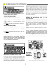
C: INSTALLING THE OPERATOR
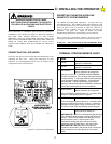
WARNING!
RISK OF ENTRAPMENT!
TO REDUCE THE RISK OF INJURY OR DEATH:
LOCATE KEYPAD, CARD READER, KEY SWITCH
OR SIMILAR ENTRY DEVICES IN A LOCATION
WHERE A USER CAN NOT REACH THROUGH THE
GATE OR FENCE TO ACTIVATE THE GATE
OPERATOR. THE RECOMMENDED DISTANCE
BETWEEN THE GATE OR FENCE AND
ACCESSORY SWITCH IS 10 FEET.
TERMINAL
STRIP
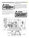
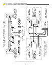
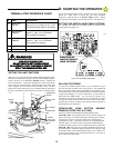
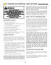
NOTE: A DEDICATED POWER SUPPLY IS
WIRING A SHADOW LOOP DETECTOR
WIRING A REVERSING LOOP DETECTOR
WIRING A FREE EXIT LOOP DETECTOR
NORMALLY OPEN
REQUIRED FOR THE DETECTOR
DRY CONTACTS
LOOP
LOOP DETECTOR
SHADOW9
FREE EXIT
24 VAC
24 VAC
2
1
5
COMMON
REVERSE
16
11
Figure 19: Wiring A Free Exit , Shadow or Reversing Loop
110123
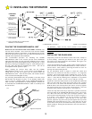
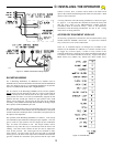
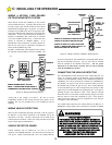
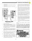
WIRING PHONE ENTRY SYSTEM
NOTE: A DEDICATED POWER SUPPLY
IS REQUIRED FOR THE ENTRY SYSTEM
DRY CONTACTS
NORMALLY OPEN
987
*
0 #
4
1
5
2
6
3
6 OPEN
2
1
5
24 VAC
24 VAC
FREE EXIT
16
STRIP
TERMINAL
COMMON
Figure 18: Wiring A Phone Entry System
110122