


12
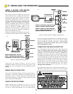
CONNECTING THE AC WIRING
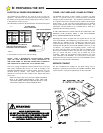
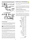
115 VOLT INSTALLATIONS:
Starting at the GS4000 Control box proceed as follows:
1. Attach to Terminal - L1 - the 115 VAC HOT wire, normally
black.
2. Attach to Terminal - L2 - 115 VAC NEUTRAL wire, normally
white.
3. The GREEN
wire attaches to the GROUND wire, normally green.
230 VOLT INSTALLATIONS:
Note: in 230 VAC wiring systems, there will be two "HOT" wires,
normally a red and a black wire. If there is a white wire, typically it
will be a neutral wire. Starting at the GS4000 4 x 4 handy box,
proceed as follows:
1. The BLACK
wire attaches to one of the 230 VAC HOT wires,
normally black.
2. The RED
wire attaches to the other 230 VAC HOT wire, normally
red.
3. The GREEN wire attaches to the GROUND wire, normally green.
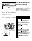
PROPER OPERATION OF THE SURGE PROTECTORS
MOUNTED ON THE GS4000 CONTROL BOARD DEPENDS
UPON A SOLID GROUND. ALSO, UL LISTING REQUIRES
THAT THE GS4000 FRAME BE GROUNDED.
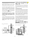
ADDITIONAL LIGHTNING PROTECTION
For those areas where a high probability of ground lightning strikes
exists (Florida, Georgia, etc,) additional lightning protection should
be installed in the GS4000. Although it may not be possible to
protect against all strikes, additional protection will substantially
reduce the occurrence of lightning damage. Allstar's lightning data
indicates that the most strikes enter the GS4000 through the power
lines. Effective protection requires that the surge current from the
lightning strike be shunted to ground. This must be done without
raising the potential of the circuitry in the GS4000, with respect to
ground, to the levels that will damage the solid state circuitry.
Lightning strikes generate enormous currents for very short periods
of time. Unfortunately, the period of time is long enough to damage
solid state components and many times, other components. The key
to success is a very low resistance path from the surge protector to
ground for these currents in addition to a surge protector that will act
fast enough to protect the solid state circuitry. Several manufacturers
offer suitable surge protectors.
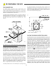
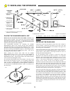
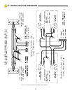
WIRING THE MECHANICAL UNIT TO THE
CONTROL BOX
It will be necessary to run two conduits from the Control Box to the
Mechanical Unit. One will be used for the A-C power lines and
another for the low voltage, class 2 wiring. See Figure 8. If wiring
one control box to one mechanical unit (standard) follow wiring as
shown in Figure 13, page 13. For bi-parting installations (one
control box and two mechanical units) see page 13 and Figure 15,
page 14.
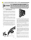
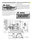
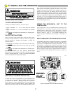
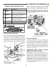
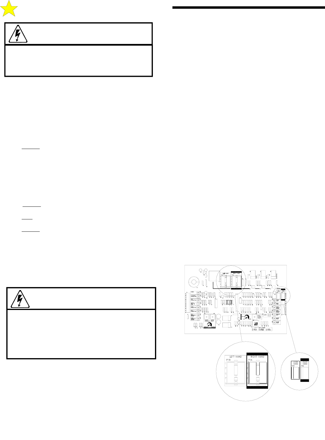
RIGHT HAND AND LEFT HAND INSTALLATION
The GS4000 Control panel is configured at the factory for right hand
operation - mechanical unit mounted to the right of the gate leaf as
you look at the installation from the inside (secured side). For left
hand operation - mechanical unit mounted to the left of the gate leaf
as you look at the installation from the inside (secured side) - move
the 8 pin high voltage harness connector (white) and the 3 pin limit
harness connector (orange) from the right hand connector blocks on
the control board to the left hand connector blocks, see Figure 12,
below.
WARNING!
RISK OF ELECTROCUTION
DO NOT BEGIN THE ELECTRICAL CONNECTION
PROCEDURES UNTIL THE POWER IS TURNED
OFF AT THE CIRCUIT BREAKER
C: INSTALLING THE OPERATOR
WARNING!
TO REDUCE THE RISK OF DAMAGE DUE TO
LIGHTNING, ENSURE A SOLID GROUND FROM
THE GS4000 GROUND WIRE IN THE SERVICE
ENTRANCE 2 x 4 HANDY BOX TO THE
ELECTRICAL SERVICE GROUND OR TO A
EARTH GROUND STAKE NEAR THE GS4000.
HIGH VOLTAGE
HARNESS
CONNECTIONS
LEFT HAND
RIGHT-HAND &
LOCATION OF
LIMITS
Figure 12: Right/Left Hand Control Board Connectors
110134