


En
12
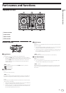
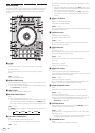
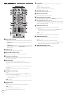
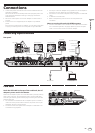
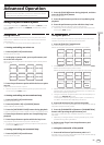
Rear panel
2 3 5 5 9 b c da
1
4 786
1 Kensington security slot
2 BOOTH output terminal
These are the output terminals for a booth monitor. Compatible with
balanced or unbalanced output for 1/4” TRS connectors.
The master channel sound can be output from the [BOOTH] output
terminals regardless of the audio level set for the master channel.
! The sound will be distorted if the level is raised too high when
using unbalanced outputs.
!
The booth monitor output is set to output the microphone sound
by default. It is possible to set not to output the microphone
sound in [Preferences] of rekordbox.
3 MASTER 2 terminals
Connect to a power amplifier, etc.
!
Compatible with RCA pin-jack type unbalanced outputs.
4 MASTER 1 terminals
Connect powered speakers, etc., here.
! Compatible with XLR connector type balanced outputs.
5 PHONO/LINE input terminals
Connect a phono level (for MM cartridges) output device (analog
player, etc.) or a line level output device (DJ player, etc.). Switch
the input source according to the connected device using the
[LINE/PHONO] switch on this unit’s rear panel.
6 LINE/PHONO switch
Selects the input source of each channel from the components con-
nected to this unit.
— [PHONO]: Select this to use a phono level (for MM cartridges)
output device (analog player, etc.) connected to the [PHONO/
LINE] input terminals.
— [LINE]: Select this to use a line level output device (DJ player,
etc.) connected to the [PHONO/LINE] input terminals.
!
Different input sources cannot be selected for both channels.
7 PC MIX switch
Switch the audio route of the external device connected to the
[PHONO/LINE] input terminal or [MIC] input terminal of this device.
= Using external inputs (p. 26 )
8 SIGNAL GND terminal
Connects an analog player’s ground wire here. This helps reduce
noise when the analog player is connected.
9 MIC input terminal
Connects a microphone here.
Compatible with a 1/4” TS jack.
a USB terminal
Connect to a computer.
! Connect this unit and the computer directly using the included
USB cable.
! A USB hub cannot be used.
b DC IN terminal
Connect to a power outlet using the included AC adapter (with the
included power cord connected).
! Connect the AC adapter after all the connections between
devices have been completed.
! Only use the included AC adapter.
c Cord hook
Catch the AC adapter’s power cord and USB cable on this hook
when using this unit.
!
The sound will be interrupted if the AC adapter or USB cable is
disconnected during playback.
d STANDBY/ON switch
This switches this unit’s power between on and standby.
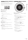
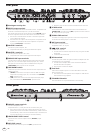
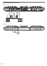
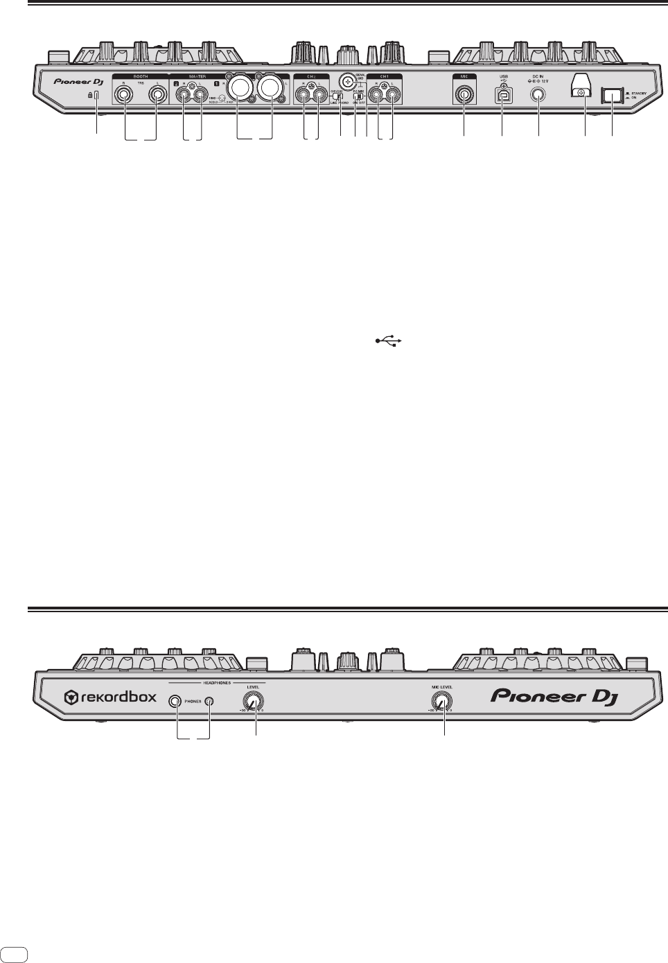
Front panel
12 3
1 PHONES output terminals
Connect headphones here.
Compatible with a 1/4” TRS jack and 3.5 mm stereo mini jack.
! There are two input jacks, both a stereo phones jack and a mini
phones jack, but do not use both simultaneously. If both are used
simultaneously, when one is disconnected and/or connected, the
volume of the other may increase or decrease suddenly.
2 HEADPHONES LEVEL control
Adjusts the level of audio output from the [PHONES] output
terminals.
3 MIC LEVEL control
Adjusts the level of audio input to the [MIC] input terminals.