SPAN Operation Chapter 3
SPAN-IGM User Manual Rev 2 31
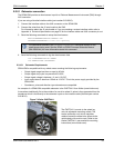
6. Alignment is complete and the INS Status field changes to INS_ALIGNMENT_COMPLETE. The
system transitions to navigation mode.
7. The solution is refined using updates from GNSS. Once the system is operating within specifications
and after some vehicle movement, the INS Status field changes to INS_SOLUTION_GOOD. This
indicates that the estimated azimuth standard deviation is below 5 degrees. If it increases above 5
degrees, the status changes to INS_HIGH_VARIANCE.
3.2.1.1 Kinematic Alignment
A kinematic alignment is the default alignment routine for SPAN-IGM. The kinematic or moving alignment
is performed by estimating the attitude from the GNSS velocity vector and injecting it into the SPAN filter
as the initial system attitude.
This method for alignment assumes that the roll and pitch of the vehicle are near to zero. This should be
kept in mind when attempting to do this in airborne or marine environments as these assumptions may
not hold causing a poor initial solution. For the kinematic alignment routine to work optimally, the course-
over-ground azimuth and pitch must match the SPAN-IGM enclosure azimuth and pitch. (For example, a
plane being blown in the wind has a a large ‘crab angle’ and the course-over ground trajectory will not
match the direction the SPAN-IGM is pointing.)
To enable kinematic alignment on the SPAN-IGM, assumptions about the system orientation have been
made in the firmware. The default orientation of the system assumes the Z-axis of the enclosure is
pointing up and the Y-axis of the enclosure is aligned with the forward axis of the vehicle. If these
assumptions are not true, additional setup commands must be sent before attempting a kinematic
alignment.
If the Z-axis is not pointing up, the correct axis orientation must be specified using the
SETIMUORIENTATION command. Refer to Table 7, Full Mapping Definitions on page 43 for possible
configurations and the SPAN on OEM6 Firmware Reference Manual (OM-20000144) for details about
the command. If the Y-axis of the system is not aligned with the forward axis of the vehicle after the
orientation is applied, then the VEHICLEBODYROTATION command must be sent. Refer to the SPAN on
OEM6 Firmware Reference Manual (OM-20000144).
Alternatively, solve the vehicle to SPAN-IGM frame angular offsets using the RVBCALIBRATE routine.
See Vehicle to SPAN Frame Angular Offsets Calibration Routine on page 33.
The kinematic alignment begins when the receiver has a good GNSS position, fine time is solved, the
configuration parameters have been set and a GNSS velocity of at least 5 m/s (~ 18 km/h) is observed.
During kinematic alignment, keep the vehicle roll at less then 10
. Straight line driving is best.
The accuracy of the initial attitude of the system following the kinematic alignment varies and depends on
the dynamics of the vehicle and the accuracy of the RVB estimates. The attitude accuracy will converge
to within specifications once some motion is observed by the system. This transition can be observed by
monitoring the INS Status field in the INS logs.
3.2.1.2 Manual Alignment
If the initial attitude (roll, pitch, azimuth) of the SPAN-IGM is known, it can be entered manually using the
SETINITATTITUDE command. Refer to the SPAN on OEM6 Firmware Reference Manual
(OM-20000144).
3.2.1.3 Dual Antenna Alignment
SPAN-IGM can also use information available from a NovAtel Dual Antenna ALIGN
®
solution to perform
an alignment. Refer to Chapter 4, SPAN-IGM Dual Antenna on page 38 for details.
The azimuth standard deviation threshold can be changed using the INSTHRESHOLDS
command. See the SPAN on OEM6 Firmware Reference Manual (OM-20000144) for
information about this command.


