14 SPAN-IGM User Manual Rev 2
Chapter 2 SPAN Installation
This chapter contains instructions and tips to setup your SPAN-IGM system.
2.1 Required Equipment
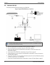
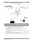
• A SPAN-IGM integrated GNSS + INS receiver
• A quality, dual frequency GNSS antenna such as the GPS-702-GG or ANT-A72GA-TW-N for
airborne/high speed applications. See the NovAtel website (www.novatel.com/products/gnss-
antennas/) for information on a variety of quality antennas available to meet your form factor and
performance needs.
• An antenna cable with a TNC male connector at the receiver end, such as NovAtel’s GPS-C016
model
• A power supply of +10 to +30 V DC with a maximum typical current of 0.4 A
For an ALIGN variant with a FlexPak6, the maximum typical current is 0.65 A
• Interface cables for the MAIN and AUX ports on the SPAN-IGM
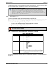
The interface cables can be NovAtel cables (see SPAN-IGM Cables on page 15) or custom built
cables (see Appendix A, Technical Specifications on page 52 for the MAIN and AUX port pin outs).
• A Windows
®
based computer with a USB or serial port
• A radio link (if your application requires real time differential operation
2.2 SPAN-IGM Hardware
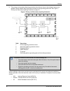
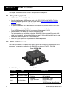
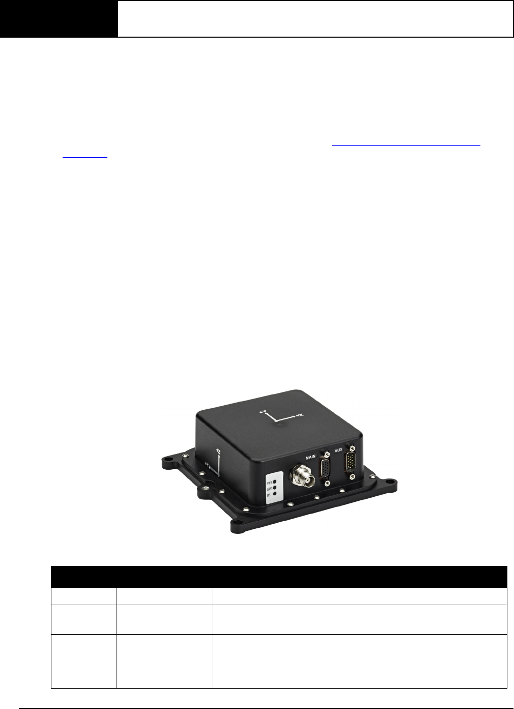
The SPAN-IGM contains an OEM615 GNSS receiver and an IMU containing 3 accelerometers and 3
gyroscopes. The connectors available on the SPAN-IGM are shown in Figure 2, SPAN-IGM.
Figure 2: SPAN-IGM
The SPAN-IGM provides one antenna and two DB-15HD connectors.
Connector Type Connections
Antenna TNC Female • GNSS antenna
MAIN DB-15HD Female
•power
•CAN Bus
•COM2 serial port
• MIC serial port
AUX DB-15HD Male
•odometer
• COM3 serial port
•USB port
• Event1/Mark 1 input
• Event2/Mark2 input
• VARF (Variable Frequency) output
• 1 PPS (Pulse Per Second) output


