SPAN Installation Chapter 2
SPAN-IGM User Manual Rev 2 15
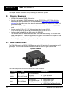
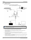
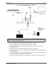
The sections that follows outline how to set up the system’s parts and cables. For more information about
the SPAN-IGM and cables, see Appendix A, Technical Specifications on page 52.
2.2.1 SPAN-IGM Cables
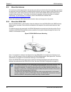
This section outlines the NovAtel interface cables used with the SPAN-IGM.
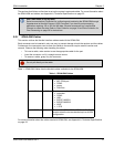
Each connector can be inserted in only one way, to prevent damage to both the receiver and the cables.
Furthermore, the connectors used to mate the cables to the receiver require careful insertion and
removal. Observe the following when handling the cables.
• To insert a cable, make certain to use the appropriate cable for the port.
• Insert the connector until it is straight on and secure.
• To remove a cable, grasp it by the connector.
Table 1, SPAN-IGM Cables lists the NovAtel cables available for the SPAN-IGM.
Table 1: SPAN-IGM Cables
For more information about the cables used with SPAN-IGM, see Appendix A, Technical Specifications
on page 52.
Use a USB cable to log raw data.
Serial communication is sufficient for configuring and monitoring the SPAN-IGM through
Hyperterminal or NovAtel Connect. USB is required if you have a post-processing
application requiring 125 or 200 Hz IMU data. We also recommend you use NovAtel
Connect to collect the data. Refer to Data Collection on page 32 and Data Collection for
Post-Processing on page 36 for instructions.
Do not pull directly on the cable.
NovAtel Part # Port Purpose
01019014 Main Provides connections for:
•MIC COM port
•COM2
•power
•CAN Bus
01019015 AUX Provides connections for:
•odometer
•COM3
•USB
• EVENT1/MARK1
• EVENT2/MARK2
•VARF
•1 PPS
01019089 Main Connects the SPAN-IGM to COM2 of a FlexPak6
receiver when the two are stacked up in an ALIGN
configuration.


