24 SPAN-IGM User Manual Rev 2
Chapter 2 SPAN Installation
SPAN-IGM powers the odometer. See Appendix A, Technical Specifications on page 52 for the pin outs
of the SPAN-IGM interface cable. Connect the appropriate pins to your chosen odometer. The cable
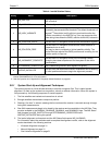
requirements are shown in Table 3, Cable Connections for Kistler CWPT Sensor on page 24.
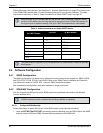
Table 3: Cable Connections for Kistler CWPT Sensor
2.4 Software Configuration
2.4.1 GNSS Configuration
The GNSS configuration can be set up for different accuracy levels such as single point, SBAS, DGPS
and RTK (RTCA, RTCM, RTCM V3 and CMR). Refer to the OEM6 Family Installation and Operation
User Manual for details on DGPS, RTK, L-band or SBAS setup and operation.
With no additional configuration, the system operates in single point mode.
2.4.2 SPAN IMU Configuration
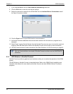
You can configure the IMU portion of the SPAN system using software commands or the NovAtel
Connect software utility.
2.4.2.1 Configure SPAN Manually
Follow these steps to enable INS as part of the SPAN system using software commands:
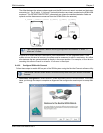
1. Issue the SETIMUTOANTOFFSET command to enter the distance from the SPAN-IGM to the GNSS
antenna, see the SPAN on OEM6 Firmware Reference Manual (OM-20000144).
Kistler provides an M12 to DB9 cable for use with the CWPT odometer. However, certain
revisions of this cable to do not bring through all four signal inputs. SPAN-IGM requires all
four signal inputs to operate correctly. See your CWPT documentation for cable details.
8-pin M12 Connector
on CWPT Sensor
Function J2 Wire Bundle
Pin 1 GND DGND
Pin 2 +U
B
(Input Power) WS-OUT
Pin 3 Signal A ODM_A+
Pin 4 Signal A inverted ODM_A-
Pin 5 Signal B ODM_B+
Pin 6 Signal B inverted ODM_B-
Pin 7 Reserved –
Pin 8
The SPAN-IGM-S1 supports only the A signals from the wheel sensor. It does not process
the B signals.
A GNSS antenna must be connected and tracking satellites for operation.


