


EN-76
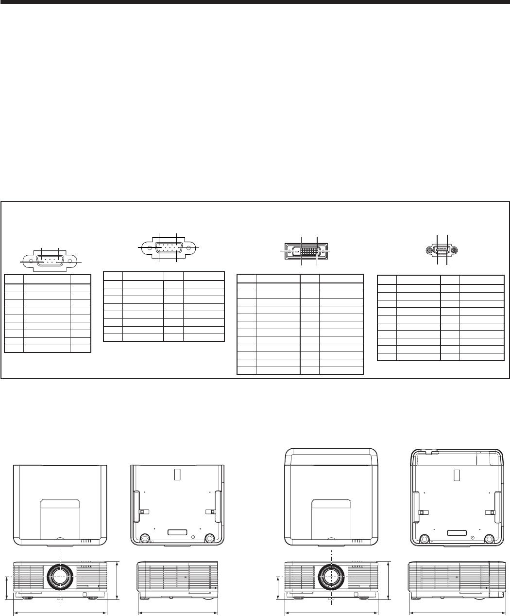
490
201
119*
421
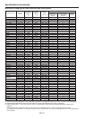
Dimension drawings (unit: mm)
Specifications (continued)
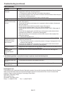
Specification of RGB signals in each computer
mode of the projector (continued)
Important:
• Some computers aren’t compatible with the
projector.
• The projector’s maximum resolution is 1024 x
768 pixels. It may not display images of higher
resolutions than 1024 x 768 correctly.
• Images with SYNC on G (Green) signal may jitter.
• Images with SYNC on G (Green) signal may be
tinged with green.
• If the resolution and frequency of your computer
aren’t shown on the table, find the compatible
resolution and frequency by changing the resolution
of your computer.
• TV60andTV50areequivalentto480iand576i
respectively. When these signals are supplied to
the VIDEO IN or S-VIDEO IN terminal, the signal
mode is indicated as TV60 or TV50. When they are
supplied to the COMPUTER/COMPONENT VIDEO
IN terminals, the signal mode is indicated as 480i or
576i.
• Thisprojectordoesn’tsupport480psignalsfrom
video devices having 4 lines (R, G, B, CS*) or having 5
lines (R, G, B, H, V).
* : Composite Sync
490
506
201
119*
Without terminal cover
With terminal cover
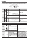
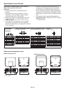
Connectors
SERIAL IN/OUT
(D-SUB 9-pin)
15
6
9
Pin No.
Name I/O
1 – –
2 TXD IN
3 RXD OUT
4 – –
5 GND –
6 – –
7 – –
8 – –
9 – –
COMPUTER/COMPONENT VIDEO
IN-1 (Mini D-SUB 15-pin)
15
11
6
10
15
Pin No.
Spec.
Pin No.
Spec.
1 R(RED)/P
R
/C
R
9 DDC 5V
2 G(GREEN)/Y 10 GND
3 B(BLUE)/P
B
/C
B
11 GND
4 GND 12 DDC Data
5 GND 13 HD/CS
6 GND 14 VD
7 GND 15 DDC Clock
8 GND
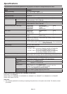
COMPUTER/COMPONENT VIDEO
DVI-D IN (HDCP)
(DVI-D 24-pin
)
1724
16
9
8
1
Pin No.
Spec.
Pin No.
Spec.
1 TMDS DATA 2- 13
-
2 TMDS DATA 2+ 14
+5V Power
3
TMDS DATA 2 Shield
15
Ground (for +5V)
4
-
16 Hot Plug Detect
5
-
17 TMDS DATA 0-
6 DDC Clock 18 TMDS DATA 0+
7 DDC Data 19
TMDS DATA 0 Shield
8
-
20
-
9 TMDS DATA 1- 21
-
10 TMDS DATA 1+ 22
TMDS Clock Shield
11
TMDS DATA 1 Shield
23 TMDS Clock+
12
-
24 TMDS Clock-
HDMI IN
(HDMI 19-pin)
19
1
2
18
Pin No.
Spec.
Pin No.
Spec.
1
TMDS Data2+
11
TMDS Clock Shield
2
TMDS Data2 Shield
12
TMDS Clock-
3
TMDS Data2-
13
CEC
4
TMDS Data1+
14
–
5
TMDS Data1 Shield
15
SCL
6
TMDS Data1-
16
SDA
7
TMDS Data0+
17
DDC Ground
8
TMDS Data0 Shield
18
+5 V Power
9
TMDS Data0-
19
Hot Plug Detect
10
TMDS Clock+
*: Factory-defaults