


11 - 19 11 - 19
MELSOFT
11. POSITIONING DEBUGGING
DISPLAY/SETTING SCREE
N
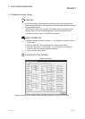
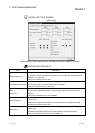
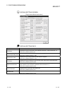
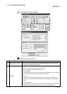
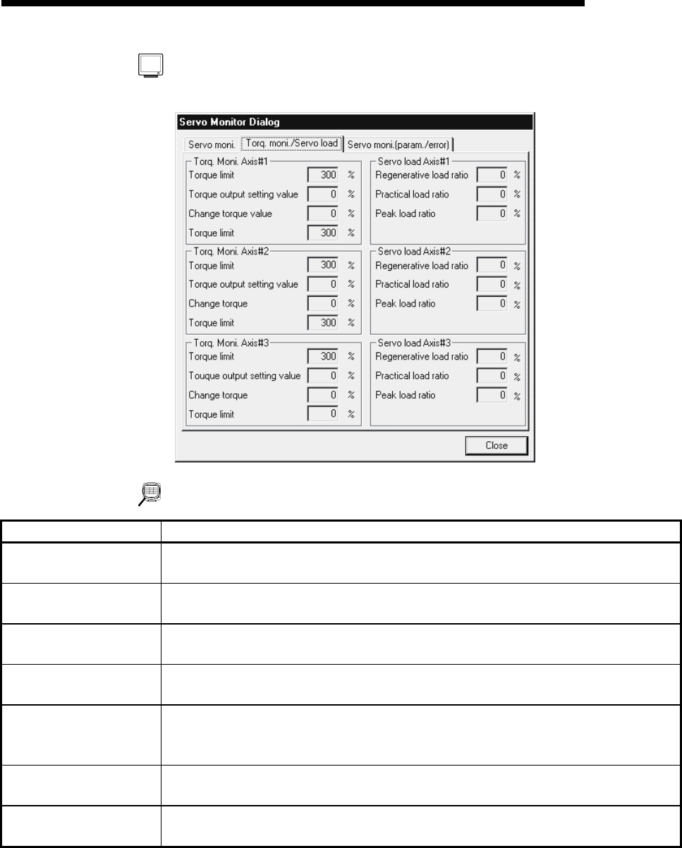
[Torque control/Servo load monitor]
DISPLAY/SETTING DATA
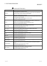
Item Description
Torque limit
Indicates the torque limit value set to the extended parameters 1 (refer to Section 8.1.3).
Buffer memory address (Axis #1): 24
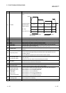
Torque output setting value
Indicates the torque output value set in the sequence program.
Buffer memory address (Axis #1): 1180
Change torque value
Indicates the torque change value set in the sequence program.
Buffer memory address (Axis #1): 1176
Torque limit
Indicates the torque limit setting or torque change value valid for the running servomotor.
Buffer memory address (Axis #1): 826
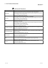
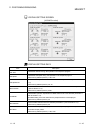
Regenerative load ratio
Indicates the ratio of the regenerative load to the permissible value of the regenerative
resistor selected in the servo basic parameters (refer to Section 8.2.1).
Buffer memory address (Axis #1): 876
Practical load ratio
Indicates the ratio of the load to the rated torque.
Buffer memory address (Axis #1): 877
Peak load ratio
Indicates the ratio of the peak load to the rated torque.
Buffer memory address (Axis #1): 878