


microKORG XL
56
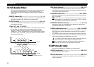
VC FILT (Vocoder Filter)
Here you can adjust the settings for the carrier’s sixteen band-pass filters
and modulator’s envelope filter. You’ll be using these parameters fre-
quently, since they play an important role in determining the character of
the vocoder.
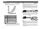
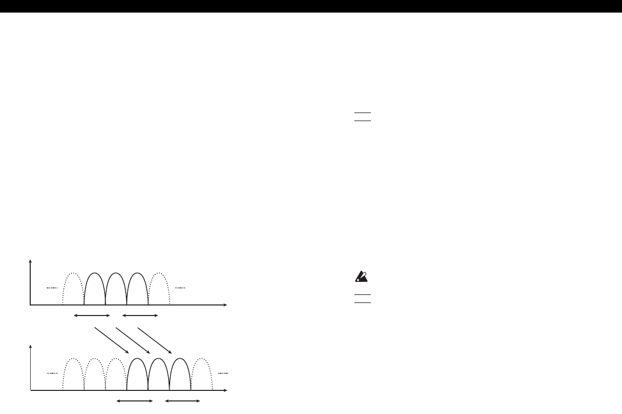
FRMNT.SFT (Formant Shift) ..................................................... [–2…+2]
Shifts the cutoff frequencies of each of the carrier’s band pass filters. This
will significantly change the character of the vocoder output.
FC.OFFSET (Fc Offset) ............................................................[–63...+63]
This continuously shifts the cutoff frequency of each band-pass filter (Syn-
thesis filter) of the carrier.
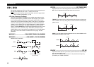
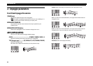
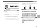
“FRMNT.SFT” and “FC.OFFSET”
Cutoff (the range in which BPF 8 will change)
0+63-63
BPFBPFBPFBPF BPFBPF
BPFBPFBPFBPF BPFBPF
897
897
Frequency
Frequency
Formant Shift:+2
Cutoff (the range in which BPF 8 will change)
0
+63
-63
When “FRMNT.SFT”=0 and “FC.OFFSET”=0, the response of the carrier fil-
ters will match the cutoff frequency of the modulator filters. The filter
response is shifted upward or downward in two discrete steps by the
“FRMNT.SFT.” This can be adjusted upward or downward a total of another
two steps by using “FC.OFFSET,” giving you a total of four steps of adjust-
ment upward or downward.
RESO (Vocoder Resonance).....................................................[000...127]
This specifies the amount of resonance for each of the carrier’s sixteen
band-pass filters (the synthesis filter). Higher settings will boost the sound
in the region of the cutoff frequency.
FC.MOD.SRC (Fc Mode Source)............................................[EG1…MIDI3]
Selects the modulation source that will be applied to the carrier band-pass
filter “FC.OFFSET.”
NOTE
The sources you can select are the same as the modulation sources for
a virtual patch (
J
p. 49 “SOURCE”). However, EG1–3, LFO1–2, VELOC-
ITY, and KEY TRK will be the sources for timbre 1.
FC.MOD.INT (Fc Modulation Intensity)....................................[–63...+63]
Specifies the depth of the modulation that is applied to the carrier band-
pass filter (Synthesis filter) “FC.OFFSET.”
EF.SENS (Envelope Follower Sens) ................................. [000...126, HOLD]
Specifies the sensitivity of the modulator’s Envelope Followers. Lower set-
tings of this value will allow the attacks of the input signal to be detected
more rapidly.
If you set this to Hold, the character of the signal that is being input at that
moment will be held (Formant Freeze). Subsequently, the sound will retain
that character regardless of whether there is any input.
If you set this to Hold when there is no input signal present, there
will
be no output even if an audio signal is subsequently input.
NOTE
If you write the program with this value set to Hold, the program will
memorize the response of the signal that was being held.
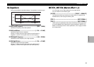
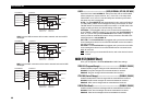
VC AMP (Vocoder Amp)
Here are the parameters for modulation and vocoder output.
VC LEVEL (Vocoder Level)........................................................[000...127]
Sets the output level of the vocoder.
DIRCT.LVL (Direct Level) .........................................................[000...127]
Sets the volume level at which the modulatior input source will be output
directly (unaffected).