


26
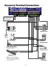
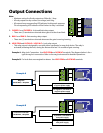
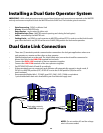
• Thesetwo(2)terminalsprovidecommunicationconnectionsfordualgateapplicationswhereone
unit operates as a master and the other as slave operator.
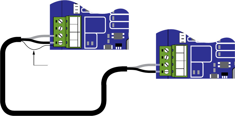
• Shieldedtwistedpairmustbeused.Theshield(drainwire)connectionshouldbeconnectedat
MasterUnitOnlytotheLINK COM terminal but not both.
• ConnecttheDUAL LINKterminalsofthetwooperatorstogether.
• ConnecttheLINK COMterminalsofthetwooperatorstogether.
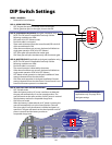
• SetOPTIONSDIPSwitch#2and#3accordingly.
• Iftheseterminalsarenotconnected,eachoperatorwillautomaticallyoperateinsinglemode,if
DIP#3isinMASTERposition(OFF).IfDIP#3issettotheSLAVEposition(ON)theunitis
non-functional.
• RecommendedBeldenWire®,22AWG,type8761,9461,9451,1266Aorequivalent.
1-pairshieldedwithdrainwire.Available at your local electrical supply store.
Dual Gate Link Connection
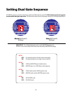
Installing a Dual Gate Operator System
IMPORTANT: With a dual gate system certain control board settings and connections are required on the MASTER
unit only and some are required on both the MASTER and the SLAVE unit. The list below gives an overview.
• Gate Sequencing-DIP#2onMasterUnit
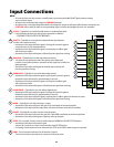
• Alarms-wiredtoMASTERonly
• Entry Devices-canbewiredtoeitherunit
• Adjustable Auto Close-MASTERcontrolsopeningandclosingforbothgates)
• Locks-controlledbytheMASTERunit
• Setting Limits-setDIP#3oneachoperatortoMASTERposition(OFF)inordertosetthelimitforeach
gate.Afterthelimitisset,DIP#3canbesettoSLAVE(ON)positionfordualmodeoperation.
ALARM
STATUS
DUAL
LINK
AT OPEN
LIMIT
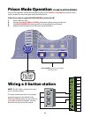
PRISON
MODE
+ ACC. PWR.
12VDC
- 300ma
ALARM
STATUS
DUAL
LINK
AT OPEN
LIMIT
PRISON
MODE
+ ACC. PWR.
12VDC
- 300ma
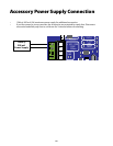
ACC. POWER
DUAL CABLE
+12Vdc
COM
DUAL LINK
LINK COM
ACC. POWER
DUAL CABLE
+12Vdc
COM
DUAL LINK
LINK COM
NOTE: Do not combine AC and low voltage
wire in the same conduit.
Drainwireconnects
at MASTER unit only.