22
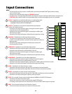
Output Connections
Note:
• Maximumratingforallrelayoutputsare24Vac/dc,1Amp.
• Allrelayoutputsaredrycontact(novoltage)switching.
• AlloutputshavecorrespondingLEDindicatorfordiagnosticpurposes.
The corresponding LED indicator will be lit when its relay is activated.
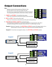
1. CLOSED 1 and CLOSED 2:Atclosedlimitrelayoutput.
• Thesetwo(2)terminalsareshortedwhengateisattheclosedlimit.
2. RUN 1 and RUN 2: Gate moving relay output.
• Thesetwo(2)terminalsareshortedwheneverthegateismoving/running.
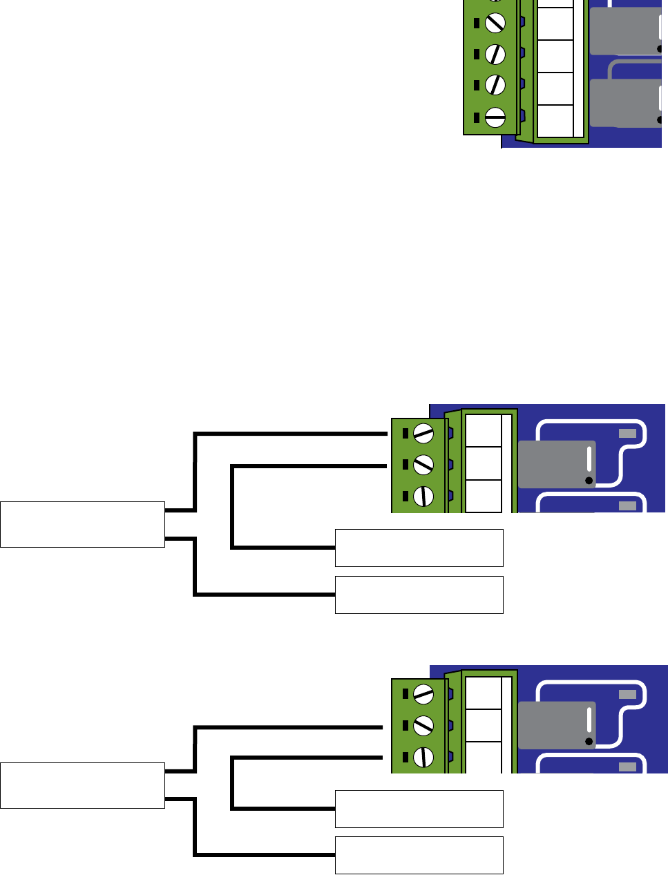
3. LOCK COM and LOCK N.O. / LOCK N.C.: Lock relay output
• Thisrelayoutputisdesignedforusewitheithermechanicalormag-lockdevice.Therelayis
activated (releasing the lock) during the rst and the last 2-4 seconds of gate running.
Example A:Mag-LockConnection:UseLOCK COM and LOCK NCterminals.Thediagrambelowisfora
typicalmag-lockconnection.Refertothemag-lockmanualfordetailedoperations.
Example B:Forlocksthatareenergizedtorelease:UseLOCK COM and LOCK NO terminals.
Lock Coil or Controller
24vDC Max, 1Amp Max
LOCK
RUNNING
CLOSED
LED11
LED10
LED09
RELAY OUTPUTS
LOCK N.C.
LOCK COM
LOCK N.O.
RUN 1
RUN 2
CLOSED 1
CLOSED 2
Example B
To positive (+) terminal of
Lock power supply
To negative (-) terminal of
Lock power supply
Mag Lock
24vDC Max, 1 Amp Max
LOCK
RUNNING
CLOSED
LED11
LED10
LED09
RELAY OUTPUTS
LOCK N.C.
LOCK COM
LOCK N.O.
RUN 1
RUN 2
CLOSED 1
CLOSED 2
To negative (-) terminal of
mag-lock power supply
To positive (+) terminal of
mag-lock power supply
Example A
RUNNING
CLOSED
LED10
LED09
RELAY OUTPUTS
LOCK N.C.
LOCK COM
LOCK N.O.
RUN 1
RUN 2
CLOSED 1
CLOSED 2


