


13
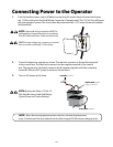
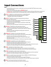
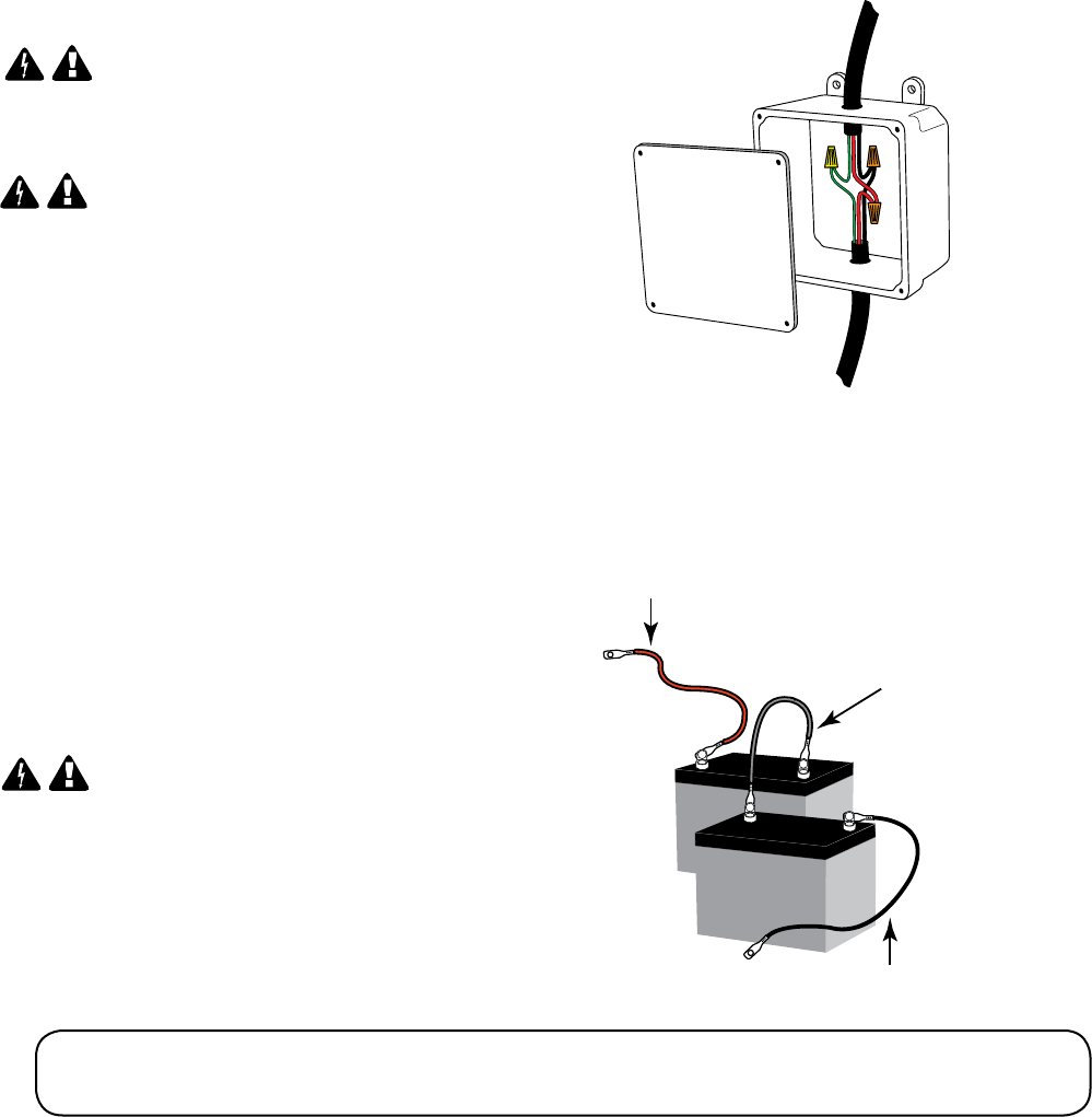
RED WIRE to positive (+)
JUMPER WIRE (Supplied)
RED WIRE to positive (+)
BLACK WIRE to negative (–)
JUMPER WIRE (Supplied)
negative (-) to positive (+)
BLACK WIRE to negative (–)
2. Connectbatteriestooperatorasshown.Theredwireconnectstothepositiveterminal
inthecontrolbox.Theblackwireconnectstothenegativeterminalinthecontrol
box.Thejumperwire(included)connectsbothbatteriestogetherwiththeremaining
terminals.Wirethe24Vsysteminseriesasshownbelow.
3. TurnonACpoweratthistime.
NOTE: Battery should be a 12 Vdc, U1,
230 Amp Minimum, Lead Acid Battery
(Typical Lawn and Tractor Battery).
NOTE: When rst turning operator power switch on, the unit may beep once
every 5 seconds until the new batteries can be fully charged (30-60 minutes charging time).
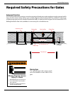
1. TurnthebreakerpowerswitchobeforeconnectingACpower.Havealicensedelectrician
run115VacwiringintotheFieldWiringConnectionCompartment.The115Vaclinewillpower
thegateoperatorsystem.Thecircuitmustbeprotectedwitha15Amaindisconnectbreaker
(not provided).
NOTE: Power and wiring connections MUST be
performed by a licensed electrician in accordance
with NEC (National Electric Code) and local codes.
NEVER run low voltage (e.g., accessory or receiver)
wires in conduit containing 115 Vac wiring.
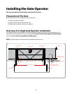
Connecting Power to the Operator