


20
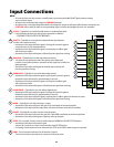
1 CYCLE:(Typicallyforusewithdoorbellbuttonorhardwiredkeypad)
• Eachactivationatthisinputwillcycletheoperationasfollows:
….→OPEN→STOP→CLOSE→STOP→OPEN→…
2 SAFETY:(Typicallyforusewithphotobeamdevice,loopdetector
or other non-contact sensors)
• Activationofthisinputwhilethegateisclosingwillcausethegateto
stop and return to the opened position.
• Activationofthisinputwhilethegateisopeninghasnoeect(gate
willcontinuetoopen).
• Activationofthisinputwhilegateisidlewillpreventgatefromclosing.
3 SHADOW:(Typicallyforusewithloopdetectordevice)
• Thisinputisonlymonitoredwhenthegateisatthefullyopen
position.Atanyotherposition,activationofthisinputhasnoeecton
gate operation.
• Activationofthisinputwhilegateatthefullyopenpositionwill
prevent gate from closing.
4 OPEN EDGE:(Typicallyforusewithsafetyedgedevice)
• Activationofthisinputwhilethegateisopeningwillcausethegateto
stop and reverse direction for approximately 2 seconds.
• Activationofthisinputwhilethegateisclosinghasnoeect(gate
willcontinuetoclose).
• Activationofthisinputwhilegateisidlewillpreventgatefromopening.
5 CLOSE EDGE:(Typicallyforusewithsafetyedgedevice)
• Activationofthisinputwhilethegateisclosingwillcausethegateto
stop and reverse direction for approximately 2 seconds.
• Activationofthisinputwhilethegateisopeninghasnoeect(gatewillcontinuetoopen).
• Activationofthisinputwhilegateisidlewillpreventgatefromclosing.
6 OPEN:(Typicallyforusewithexitlooporwand)
• Activationofthisinputwillopenthegateifit’snotalreadyattheopenposition
• Activationofthisinputwhileatopenlimitwillrestarttheautoclosetime(ifenabled).
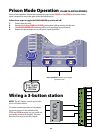
7 CLOSE:(Typicallyforusewith3-buttoncontrolstation)
• ActivationofthisinputwillclosethegateifitisidleANDnotalreadyattheclosedposition.
• Activationofthisinputwhilegateisopeningwillstopthegate.
8 STOP:(Forusewith3-buttoncontrolstationthathas‘NORMALLYCLOSED’STOPbutton)
• Activationofthisinputwillstopthegate.
• Jumper‘W1’mustbecutwhenusingnormallyclosed‘STOP’button.
• Anormallyclosedbuttonmustbeconnectedto‘STOP’and‘COM’inorderforgatetooperate.
9 COM: Circuit common (reference for all accessory inputs)
• Three(3)terminalstoprovideextracommonconnectionpoint.
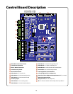
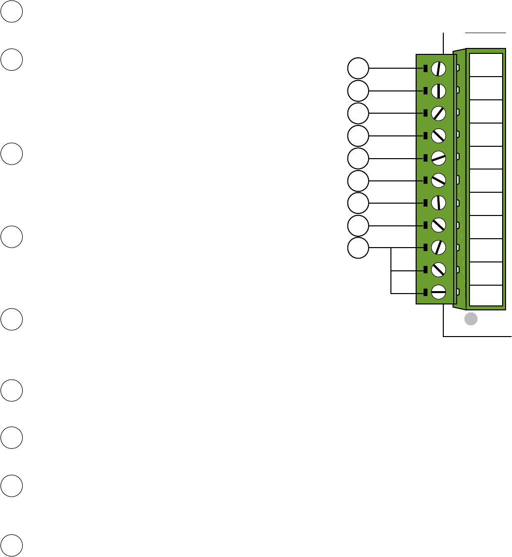
Input Connections
1 2 3 4
ON
LOCK
COM
COM
COM
ALARM
CYCLE
SAFETY
SHADOW
OPEN
CLOSE
STOP
OPEN
EDGE
CLOSE
EDGE
STATUS
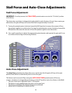
STALL FORCE ADJUST
LIMIT ADJUSTMENTS
DUAL
LINK
GTO LOOP DETECTORS
LIMIT SENSORS
DIAG.
PORT
BLDC SPEED CONTROL
EXIT SHADOW SAFETY
AT OPEN
LIMIT
PRISON
MODE
RUNNING
OPTIONS
TEST SWITCHES
CLOSE STOP OPEN
GTO Inc. Tallahassee, FL
SX4000 Logic Board Rev. E
MIN MAX MIN MAX OFF 120
<<<
JOG
>>>
<<<
>>>
SET
LIMIT
CLOSED
LED11
LED10
LED09
+ ACC. PWR.
12VDC
- 300ma
W1
CUT TO USE
3 BUTTON
STATION
AUTO CLOSE
TIMER
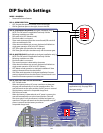
MODE 1
MODE 2
OPEN DIR.
SLV OPN
DUAL MODE
LOW BATT
ON
ON
>>>
SIMUL
SLAVE
SECURE
OFF
OFF
<<<
DELAY
MASTER
SAFE
ACC. POWER DUAL CABLE
+12Vdc
COM
DUAL LINK
LINK COM
RELAY OUTPUTS
LOCK N.C.
LOCK COM
LOCK N.O.
RUN 1
RUN 2
CLOSED 1
CLOSED 2
CYCLE
SAFETY
OPEN EDGE
CLOSE EDGE
OPEN
CLOSE
STOP
COM
COM
COM
SHADOW
LOOP
1
2
3
4
5
8
9
6
7
NOTE:
• Allcontrolinputsaredry-contact,normallyopen,inputsexceptfor#8. DO NOT apply external voltage
sources to these inputs.
• AllinputsareconnectedwithrespecttoCOMMON terminal.
• AllinputshaveacorrespondingLEDindicatorfordiagnosticpurposes.AllinputLEDindicators,exceptforthe
STOP LED,willbedimlylitwhenitscorrespondinginputisinactiveandbrightlylitwhenitisactivated.