


Hopper Loaders with/without Sight Glasses 14
5. On 115 VAC control voltage systems, run a common hot (115 VAC) wire and
a common neutral wire from the controller to each pump package in the
system.
On 24 VDC control voltage systems, run a common +24 VDC wire and a
common 0 (zero) VDC wire from the controller to each pump package in the
system.
Note: Reference “Mechanical Components Operation and Installation
manual” for more details on component locations (manual part #
A0536580).
3-5 Set-up
This section provides the procedures for configuring your 2-pump, 20-
station controller.
Configuration of your controller includes setting the number of stations
and pumps, setting variables such as convey time and blow-back interval,
and setting up passwords. We recommend that you carry out these
procedures in the order given here.
Note: Before carrying out these procedures, install all equipment as described
in this section and in the Mechanical Components manual.
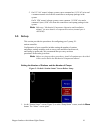
Setting the Number of Stations and the Number of Pumps
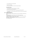
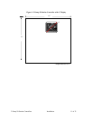
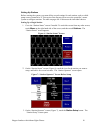
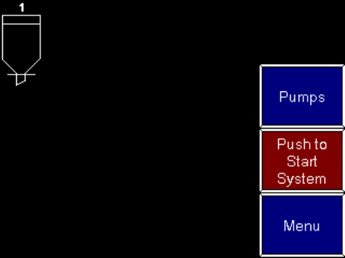
Figure 2: Default “Station Status” Screen Before Setup
1. At the “Station Status” screen (Figure 2) or at the “Pump Status” screen, touch the Menu
button. The “Menu” screen opens.