


2–Pump 20-Station Controllers Installation 13 of 51
3-4 Electrical Connections
Refer to local electrical codes, the schematic and connection diagrams supplied with this
unit and the serial tag for wiring considerations. Run all wiring in conduit if codes require
it.
Making Control Panel Power Drop Wiring Connections
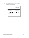
Hardwire the input power at 110/1/50-60 VAC or 230V/1/50-60 VAC, depending on the
specifications, which are located on the Control Panel Serial Tag. The main power
switch is located on the front of the enclosure.
Caution! We recommend that you protect PLC memory by providing the control
panel with a dedicated circuit, a true earth ground, and a spike/surge
protector.
Connecting the Control Panel to Vacuum Hoppers
Note: Wire size depends on control voltage, distance, number of vacuum
hoppers, and the number of wires in each raceway. Consult a qualified
electrician.
1. On 115 VAC control voltage systems, run a common hot (115 VAC) wire and
a common neutral wire from the controller to each vacuum hopper in the
system.
On 24 VDC control voltage systems, run a common +24 VDC wire and a
common 0 (zero) VDC wire from the controller to each vacuum hopper in the
system.
2. On all systems, run two wires to each vacuum hopper: one each from the
controller to the Bin-Full switch (LS) and to the Atmospheric/Sequence-T
solenoid (SOL) valve.
3. Make sure that the solenoid and the proximity switch (if supplied) on vacuum
hoppers are the same voltage as the control panel voltage. Consult the control
panel serial tag and the solenoid valve nameplates.
4. Wire size depends on control voltage, distance, number of vacuum hoppers,
and the number of wires in each raceway. Consult a qualified electrician.
5. Properly ground each hopper to reduce static build up generated by material
conveying.
Connecting the Control Panel to the Pump Package
1. Wire the pump package motor starter coil (M) to the terminal provided in the
control panel enclosure.
2. Wire the pump package vacuum relief valve solenoid (SOL A) to the terminal
provided in the control panel enclosure.
3. Wire the pump package vacuum switch (VS) to the terminal located in the
control panel enclosure.
4. On vacuum pumps, wire the pump package blowback solenoid (SOL B) to the
terminal located in the control panel enclosure.