Commander GP User Guide
Issue code: gpxu2
Setting Up the Drive 3-45
3.10 Macro 7
Brake control
Features
Specific features
Brake control is used for controlling the application
and release of a mechanical brake in hoist or crane
applications. The Drive issues a brake release signal
when all of the following conditions are met:
• The Drive has not tripped (ie. healthy)
• The output frequency of the Drive is
above 1Hz
• Current above a user-defined threshold is
being supplied to the motor in order to hold
or move the load
The brake release signal can be delayed by an amount
that is adjusted by the user. This delay is used to
ensure that only genuine conditions will cause the
brake to be released.
The Drive applies the brake, by removing the brake
release signal, as the motor is stopping and motor
current falls below the threshold level.
The Drive is operated under frequency control;
selection can be made between local and remote
sources, as well as keypad control.
Standard features
• Macro 7 can be operated in Terminal mode
(default) or Keypad mode
• Digital control by RUN FORWARD, and
RUN REVERSE contacts
• Analog frequency inputs
• Adjustment of minimum and maximum
frequencies
• Adjustment of acceleration and
deceleration ramps
• Motor thermistor input
• SPEED and TORQUE analog outputs
• External trip digital input
• Drive RESET digital input
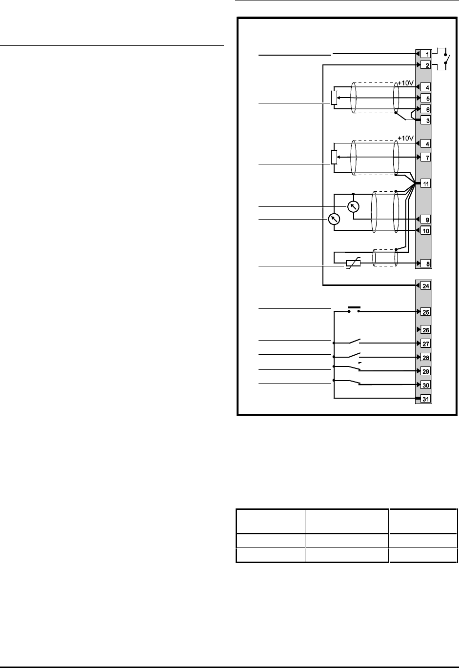
Signal connections for Macro 7
0V common
Analog frequency
reference 1
(remote) 0 ~ 10V
SPEED
TORQUE
0V common
BRAKE RELEASE
RESET
RUN FORWARD
External trip
0V common
REMOTE
LOCAL
RUN REVERSE
LOCAL / REMOTE
Signal
connector
Analog frequency
reference 2
(local) 0 ~ 10V
Motor thermistor
Figure 3–17 Control signal and thermistor
connections for Macro 7
The BRAKE RELEASE output must be connected as
shown in Figure 3–17. Note that the actual BRAKE
RELEASE output appears on terminal 24 which
operates as shown in the following table.
Terminal 24
Effect
Low
Release brake
High
Apply brake
For electrical specifications, refer to Appendix C
Signal Connections.


