Commander GP User Guide
Issue code: gpxu2
Setting Up the Drive 3-27
3.7 Macro 4
Torque control
Features
Specific features
Selection can be made between torque control and
frequency control.
When frequency control is selected, the Drive will
run at the frequency demand irrespective of load so
long as the maximum permissible output current of
the Drive is not reached. The frequency reference
must be applied to analog input 2.
When torque control is selected, analog input 1 is
configured for an analog torque reference. The
maximum frequency is limited to the value of
0.02 Maximum frequency. Analog input 2 is not used.
Both inputs accept 0 to 10V.
Torque slaving
Macro 4 can be used in applications where two or
more motors are mechanically linked and must share
the torque load in a controlled way.
Standard features
• Macro 4 operates in Terminal mode only
• Digital control by RUN FORWARD and
RUN REVERSE contacts
• Analog torque and frequency inputs
• Adjustment of maximum frequencies
• Adjustment of acceleration and deceleration
ramps
• Operation of the status relay can
be inverted
• Selection of braking mode
• Motor thermistor input
• Negative logic for the digital inputs
• SPEED and TORQUE analog outputs
• AT MINIMUM SPEED digital output
• AT SPEED digital output
• External trip digital input
• Drive RESET digital input
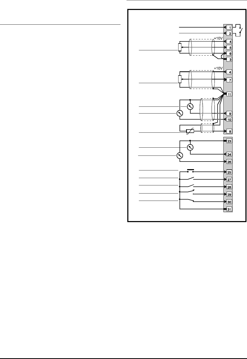
Signal connections for Macro 4
Status relay
Drive healthy
Analog torque
reference 1 (0 ~ 10V)
Motor thermistor
SPEED
TORQUE
0V common
AT SPEED
RESET
AT MIN. SPEED
RUN FORWARD
RUN REVERSE
TORQUE ENABLE
External trip
0V common
0V common
FREQUENCY CONTROL
TORQUE CONTROL
0V common
Signal
connector
Analog frequency
reference 1 (0 ~ 10V)
Figure 3–10 Control signal and thermistor
connections for Macro 4
For electrical specifications, refer to Appendix C
Signal Connections.


