Commander GP User Guide
Issue code: gpxu2
Setting Up the Drive 3-43
Setting up and using Macro 6
The following may require attention in addition to
the settings made in Chapter 2.
Frequency control
When Macro 6 is selected, the Drive always operates
in axis-limit control; unlike Macros 2 to 5, no digital
input exists to allow switching to and from normal
frequency control.
Operation in bipolar or unipolar frequency control is
dependent only on the signal connections made.
When bipolar control is required, to prevent
confusion do not connect a RUN REVERSE contact.
No jog function exists.
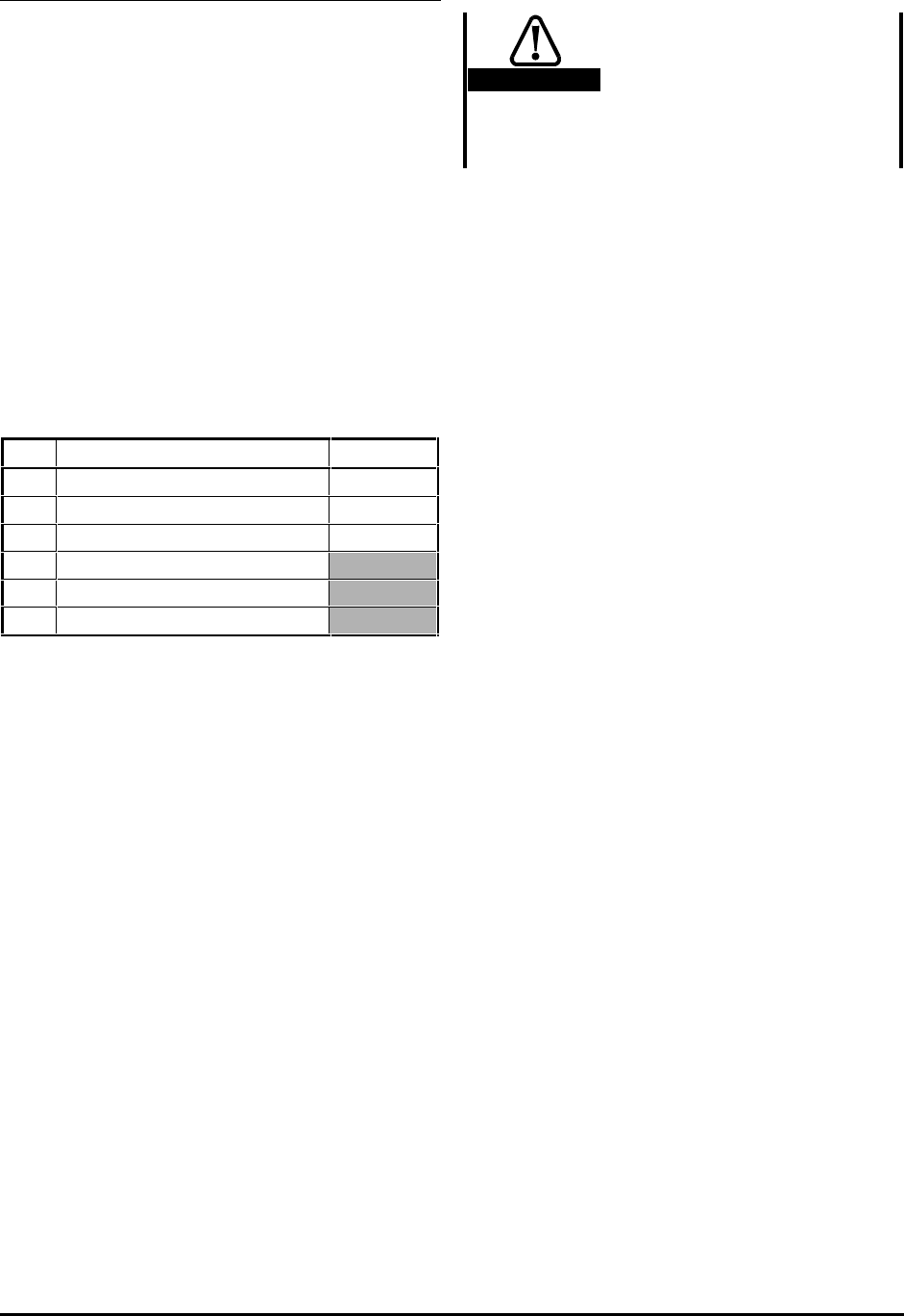
Reference selection
Use 0.05 Reference selector to select the required
frequency reference source, as follows:
0.05 Source Terminal(s)
0 Analog input 1 (bipolar or unipolar) 5, 6
1 Analog input 1 (bipolar or unipolar) 5, 6
2 Analog input 2 (unipolar only) 7
3 (Do not use)
4 (Do not use)
5 (Do not use)
Analog input mode
The analog inputs are configured for 0 ~ 10V.
See the Commander Gp Advanced User Guide for
selecting other modes.
Limit switch types
By default, the Drive requires normally-open limit
switches. When either or both limit switches are to
be normally-closed, set the following parameters
at 1, as appropriate:
LIMIT FORWARD 0.21
LIMIT REVERSE 0.22
Deceleration rates
Caution
Position the limit switches
to allow for the distance
that will be travelled during
deceleration. This distance
will be increased if the
deceleration time is
extended (see Braking mode).
The rate of deceleration to be applied when the
motor is being stopped at the limit of travel can be
adjusted separately from the normal deceleration
rate, as follows:
Use 0.04 Deceleration rate for adjusting the
maximum deceleration rate that is to apply when
any of the following occurs:
• The motor is stopped by removal of a RUN
command
• The motor is stopped or slowed by
reduction of the frequency reference
For setting the deceleration rate at the limit of
travel, use parameter 0.20 Limit deceleration rate.
Braking mode
The FASt ramp mode is applied. This gives
continuous deceleration under maximum braking
conditions (the ramp mode should not be changed).
A braking resistor is normally required in order to
prevent the
DC-bus voltage from reaching the trip
level.
Stopping modes
Refer to parameter 0.18 Stop mode selector in
Appendix D Menu 0 Parameters.
Hold zero speed
Refer to parameter 0.19 Hold zero speed enable in
Appendix D Menu 0 Parameters.
The default setting is 0 (Free to
rotate).


