


En
7
Connections and part names
Connections and part names
Connections
Be sure the power is off when connecting equipment and changing
connections.
Be sure to use the USB cable included with this product.
Refer to the operating instructions for the component to be connected.
With this unit, the power is supplied by USB bus power. The unit can be
used simply by connecting it to a computer using the USB cable.
! Connect the computer to which this unit is to be connected to an AC
power supply.
! A USB hub cannot be used.
! In cases like the ones below, the power may be insufficient and this
unit may not operate on USB bus power.
— When the computer’s USB power supply capacity is insufficient.
— When other USB devices are connected to the computer.
— When headphones with an impedance of less than 32 W are
connected.
— When headphones are simultaneously connected to the stereo
phone jack and the stereo mini-phone jack.
— When a monaural jack is connected to the [HEADPHONES] terminal.
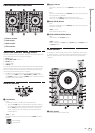
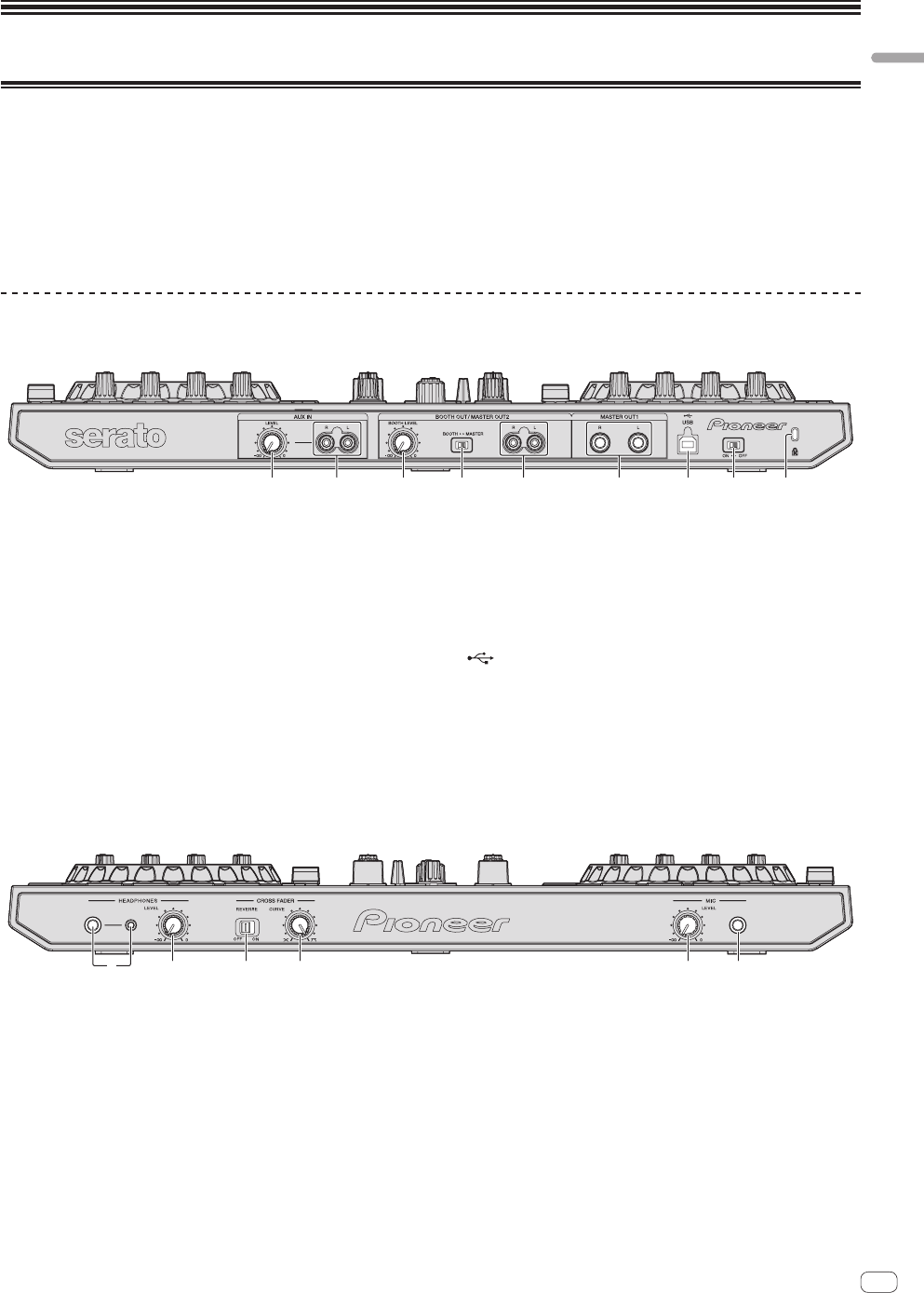
Names of Parts
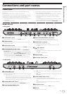
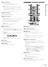
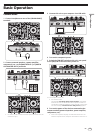
Rear panel
1 2 5 63 4 7 89
1 AUX IN LEVEL control
Adjusts the audio level input to the [AUX IN] terminals.
2 AUX IN terminal
Connect to the output terminal of an external device (sampler, por-
table audio device, etc.)
3 BOOTH LEVEL control
Adjusts the level of audio signals output from the [BOOTH] terminal.
4 BOOTH/MASTER selector switch
Switches between outputting the sound from the [BOOTH OUT/
MASTER OUT 2] terminals for booth monitoring and outputting the
master channel. When set to the [BOOTH] side, the master channel
sound is output from the [BOOTH OUT/MASTER OUT 2] terminals,
regardless of the audio level set for the master channel. The volume
level can be adjusted with the [BOOTH LEVEL] control.
! The sound will be distorted if the volume level is set too high.
5 BOOTH OUT/MASTER OUT 2 terminals
Connect to a power amplifier or booth monitor, etc.
! Compatible with RCA pin-jack type unbalanced outputs.
6 MASTER OUT 1 terminals
Connect powered speakers, etc., here.
! Compatible with balanced or unbalanced output for a TRS
connector.
7 USB terminal
Connect to a computer.
! Connect this unit and the computer directly using the included
USB cable.
! A USB hub cannot be used.
8 ON/OFF switch
Turns this unit’s power on and off.
9 Kensington security slot
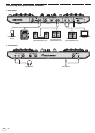
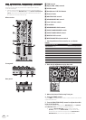
Front panel
12 63 4 5
1 HEADPHONES jacks
Connect headphones here.
Both stereo phone plugs (Ø 6.3 mm) and stereo mini phone plugs (Ø
3.5 mm) can be used.
! There are two input jacks, both a stereo phones jack and a mini
phones jack, but do not use both simultaneously. If both are used
simultaneously, when one is disconnected and/or connected, the
volume of the other may increase or decrease suddenly.
2 HEADPHONES LEVEL control
Adjusts the audio level output from the [HEADPHONES] terminal.
3 CROSS FADER REVERSE switch
Switches the crossfader left/right.
! [ON]: The left side of the crossfader is for deck [2], the right side
for deck [1].
! [OFF]: The left side of the crossfader is for deck [1], the right side
for deck [2].
4 CROSS FADER CURVE control
This switches the crossfader curve characteristics.
! The further the control is turned clockwise, the sharper the curve
rises.
! The further the control is turned counterclockwise, the more
gradually the curve rises.
5 MIC LEVEL control
Adjusts the audio level input to the [MIC] terminal.
6 MIC jack
Connects a microphone here.