


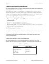

Chapter 10 Easy I/O for DAQ Library
© National Instruments Corporation 10-11 LabWindows/CVI Standard Libraries
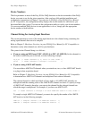
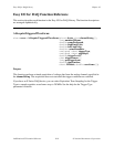
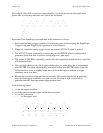
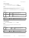
For example, if the A/D conversions (represented by x's) on the waveform shown below are
placed side-by-side, they represent one cycle of the waveform.
_ _ _ x _ _ _
/ \ / \ x \ / \ / x / \ / \
/ \ x \ / \ / \ / \ / x / \
x \_/ \_/ \_/ \_/ \_/ \_/ x_/
x
x x
x x
x x
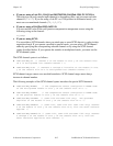
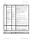
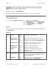
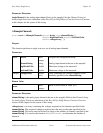
Equivalent Time Sampling is accomplished in this function as follows:
1. Set a hardware analog trigger condition for measuring your waveform using the Edge/Slope,
Trigger Level, and Trigger Source parameters of this function.
2. Whenever a hardware analog trigger occurs, the internal ATCOUT signal is strobed.
3. The ATCOUT signal is internally routed to the gate of GPCTR0, which is configured to
generate a pulse each time it receives a rising edge at it's gate input.
4. The output of GPCTR0 is internally routed to the data acquisition sample clock to control the
A/D conversion rate.
5. The very high effective scan rate is achieved through a pre-pulse delay that is programmed
into GPCTR0. This delay automatically increments before each GPCTR0 pulse so that the
A/D conversions occur at slightly larger intervals from the trigger condition as trigger
conditions occur over time.
6. Because the waveform being measured is periodic, A/D conversions that are at particular
intervals from trigger conditions over time can look the same as A/D conversions at
particular intervals from one unique trigger point in time.
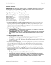
In the following figure:
tn => the nth trigger condition
dn => delay between the nth trigger and the nth conversion
x => an A/D conversion
- - - => the trigger level
_ _ _ x _ _ _
/ \ / \ x \ / \ / x / \ / \
/ \ x \ / \ / \ / \ / x / \
x- - -\-
/- - -\-/- - -\-/- - -\-/- - -\-/- - -\-/- - -x-/-
________________________________________________________
t0 t1 t2 t3 t4 t5 t6
|| |-| |--| |---| |----| |-----| |------|
d0 d1 d2 d3 d4 d5 d6