


Chapter 5 RS-232 Library
© National Instruments Corporation 5-5 LabWindows/CVI Standard Libraries
All serial devices are either of the type Data Communication Equipment (DCE) or Data
Transmission Equipment (DTE). The PC is of type DTE. The difference between the two
devices is in the meaning assigned to the pins. A DCE device reverses the meaning of pins 2 and
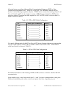
3, 4 and 5, and 6 and 20. In the simplest scenario, a DTE device is attached to a DCE device,
such as a modem. Therefore, the cable required for a PC (or DTE) to talk to a device that is a
DCE is shown in Table 5-3.
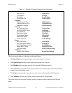
Table 5-3. DTE to DCE Cable Configuration
(PC) Connect pins as indicated: (Device)
TxD* 2
_______________
2 RxD
RxD 3
_______________
3 TxD*
RTS* 4
_______________
4 CTS
CTS 5
_______________
5 RTS*
DSR 6
_______________
6 DTR
DTR* 20
______________
20 DSR*
common 7
_______________
7 common
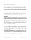
You need a different cable for the PC to talk to a DTE device, because both devices transmit data
over pin 2. The cable to connect a PC to a DTE is called a null modem cable. A null modem
cable must be built as shown in Table 5-4.
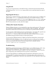
Table 5-4. PC to DTE Cable Configuration
(PC) Connect pins as indicated: (Device)
TxD* 2
_______________
3 RxD
RxD 3
_______________
2 TxD*
RTS* 4
_______________
5 CTS
CTS 5
_______________
4 RTS*
DSR 6
_______________
20 DTR
DTR* 20
______________
6 DSR*
common 7
_______________
7 common
For further information on the meaning of DTE and DCE, refer to a reference book on RS-232
communication.
In the simplest case, a serial cable needs lines 2, 3, and 7 for basic communication to take place.
Hardware handshaking and modem control can require other lines, depending on your