


2-9
Static Virtual LANs (VLANs)
Static VLAN Operation
VLAN Operation
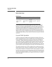
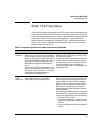
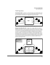
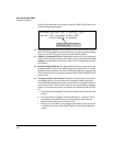
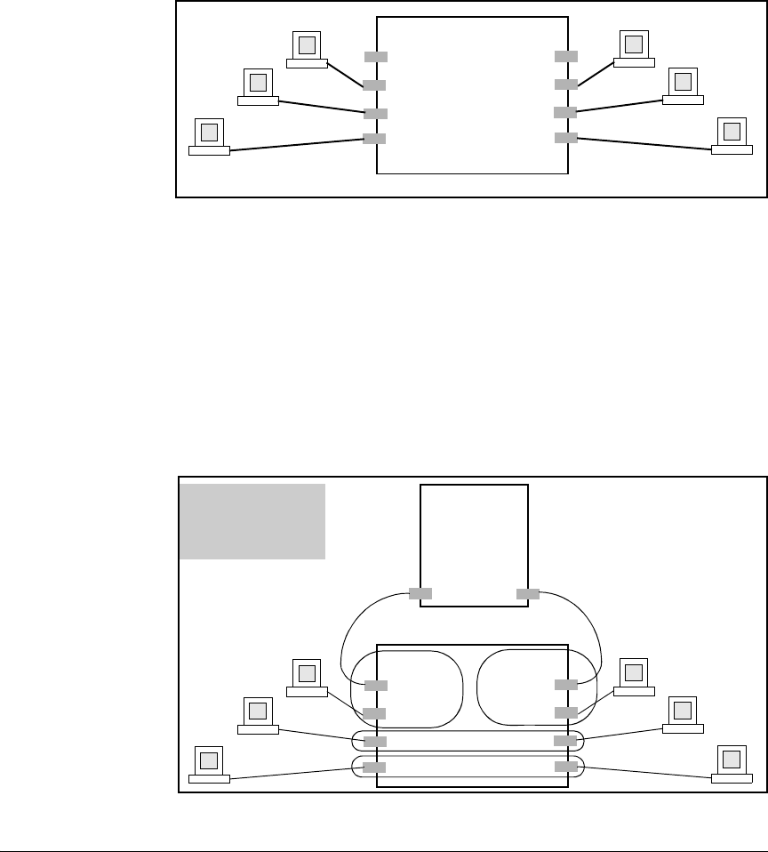
The Default VLAN. In figure 2-1, all ports belong to the default VLAN, and
devices connected to these ports are in the same broadcast domain. Except
for an IP address and subnet, no configuration steps are needed.
Figure 2-1. Example of a Switch in the Default VLAN Configuration
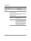
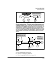
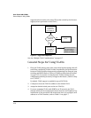
Multiple Port-Based VLANs. In figure 2-2, routing within the switch is
disabled (the default). This means that communication between any routable
VLANs on the switch must go through the external router. In this case, VLANs
“W” and “X” can exchange traffic through the external router, but traffic in
VLANs “Y” and “Z” is restricted to the respective VLANs. Note that VLAN 1,
the default VLAN, is also present, but not shown. (The default VLAN cannot
be deleted from the switch. However, ports assigned to other VLANs can be
removed from the default VLAN, if desired.) If internal (IP) routing is enabled
on the switch, then the external router is not needed for traffic to move
between port-based VLANs.
Figure 2-2. Example of Multiple VLANs on the Switch
VLAN 1
A2
A3
A4
A7
A6
A5
A1
A8
External
Router
Switch with Multiple
VLANs Configured
and Internal Routing
Disabled
A2
A3
A4
A7
A6
A5
A1
A8
VLAN Z
VLAN Y
VLAN X
VLAN W