


3. Physical installation
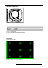
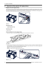
Scheimpflug adjustment points
4
1
2
3
d
D
c
C
A
a
B
b
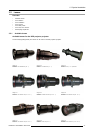
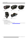
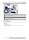
Image 3-35
Scheimpflug adjustments
Indication on drawing Function
4 Locking nut
1, 2 and 3 Scheimpflug adjustment nuts
A, B, C and D Set screws
a, b, c and d lock nuts
1, 2 and 3 are adjustment points.
4 is a locking point and NOT used during Scheimpflug adjustment.
Necessary tools
• Allenkey3mm
• Nut driver 13 mm
• Nut driver 10 mm
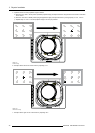
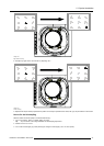
How to adjust
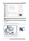
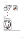
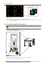
1. Project a green focus pattern.
Image 3-36
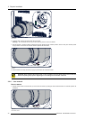
2. Loosen the lock nuts (a, b, c and d). See image 3-35.
3. Loosen the 4 set screws (A, B, C and D) by 1 cm. See image 3-35.
4. Fully loosen lock nut 4. See image 3-35.
R5905032 HDX SERIES 05/12/2014
35