


Digital Dosing Units
12
be exposed to extreme heat (maximum temperature 45°C or 115°F) or excessive
moisture.
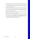
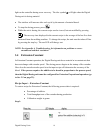
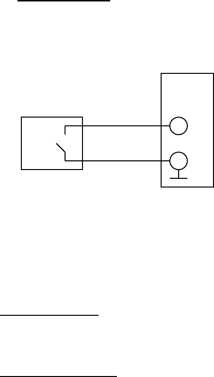
4. Electrical connection to process machine:
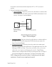
• Injection Molding: Connect the cycle/run slave cable (thin two-conductor cable)
to a set of DRY (NO VOLTAGE) contacts that CLOSE for the duration of screw
recovery. See Figure 5, electrical diagram.
J12-3
J12-2
Relay contact
Injection molding Digital Dosing controller
Machine
(Electrical diagram of connections)
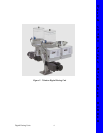
Figure 5. Electrical Diagram
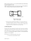
• Extrusion-Constant: Wire the cycle/run slave cable (thin two- conductor cable) to a
set of DRY (NO VOLTAGE) contacts that CLOSE when the screw rotates. See
Figure 6 for electrical diagram.
• Extrusion-Proportional
: Wire the cycle/run slave cable to the extruder signal
output that is proportional to the extruder speed. The signal output can be one of the
following: 0-10VDC or 0-20mA. Please refer to the labels on the cycle/run slave
cable for the correct input to avoid damaging the controller. Digital Dosing
Additive Feeder is configured from the factory for each specific input. See Figure 5
for the electrical diagram for voltage inputs. See Figure 6 for frequency inputs.
NOTE: Voltage from Drive needs to be isolated. Consult factory for other signal
requirements. External converter signal may be required.