


11 - 14 11 - 14
MELSOFT
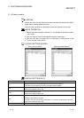
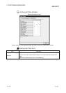
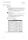
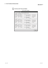
11. POSITIONING DEBUGGING
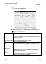
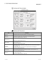
DISPLAY/SETTING DATA
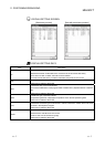
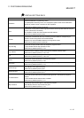
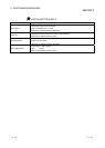
Item Description
Target speed
Indicates the target speed for positioning data operation, OPR or JOG operation.
For interpolation control, the comp. speed or longer axis speed is displayed at the reference
axis and 0 appears at the interpolation axis.
Buffer memory address (Axis #1): 820, 821
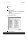
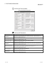
Axis speed
Shows the speed of the axis operating actually in any operation.
For interpolation control, the comp. speed or longer axis speed is displayed at the reference
axis and 0 appears at the interpolation axis.
Buffer memory address (Axis #1): 804, 805
Current
Indicates the current speed.
For interpolation control, the comp. speed or longer axis speed is displayed at the reference
axis and 0 appears at the interpolation axis.
0 represents JOG operation or MPG operation.
Buffer memory address (Axis #1): 810
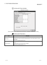
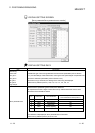
Travel after V/P switched
ON
Indicates the travel distance under position control when speed control is changed to position
control during speed/position switching control.
Buffer memory address (Axis #1): 814, 815
Travel correction register
Indicates the value set to the speed/position switching control travel correction register in the
sequence program.
Buffer memory address (Axis #1): 1164, 1165
V/P switch latch
Indicates the speed/position switching latch flag for the status signal. Turned z (ON) when
speed control is switched to position control.
Buffer memory address (Axis #1): 817
Switch
Indicates the speed/position switching enable flag set in the sequence program.
z (ON) indicates that switching by the speed/position switching signal is valid.
Buffer memory address (Axis #1): 1163
V-control
Indicates the signal for differentiating between speed control and position control.
z (ON) during speed control.
Buffer memory address (Axis #1): 830