


SERVICE
32
p/n GH 19502091
Fig. 59
Fig. 58
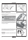
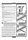
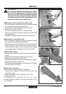
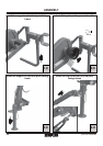
Replacement of bar holding removable tooth
• With the implement resting on the ground, raise the mowing
bar and secure it with the hooking tie rod.
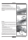
• Unscrew all the tooth fastening screws (Fig. 58).
• Remove all the teeth (Fig. 59).
• Remove the expansion pin and slide out the bar.
• Insert the new tooth-holding bar and lock it in place with
the expansion pin.
• Reposition the teeth and fasten them with the screws.
Replacement of removable tooth
• With the implement resting on the ground, raise the mowing
bar and secure it with the hooking tie rod.
• Unscrew the screws of the tooth to be replaced (Fig. 58).
• Slide out the tooth (Fig. 59), put in the new one and lock it
in place with the screws. For this it would be advisable to
use a torque wrench, respecting the values of 30 Nm.
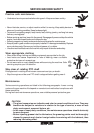
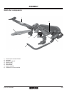
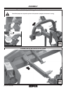
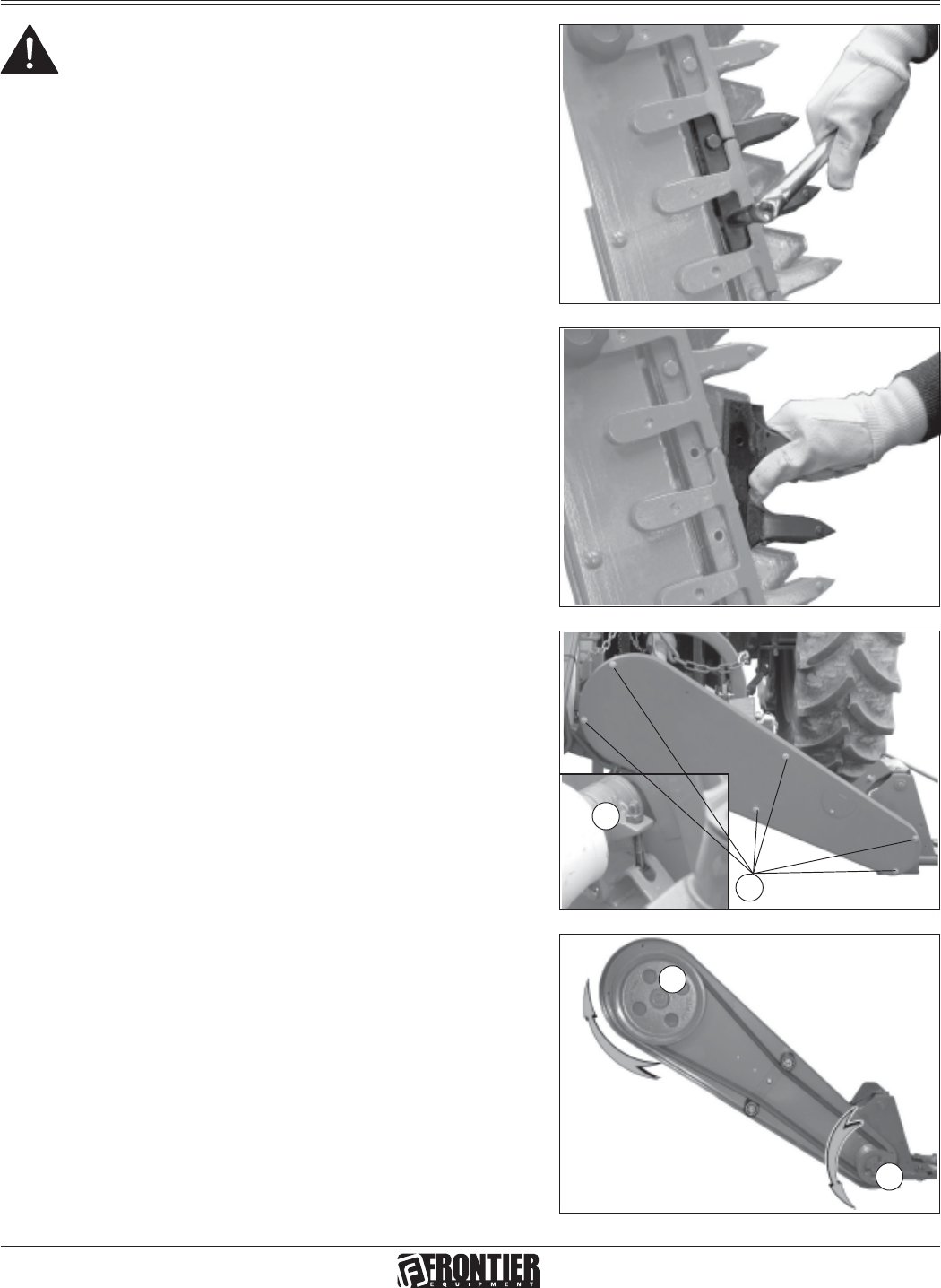
Replacement of belts
• Unscrew the screws (A Fig. 60) and remove the protective
casing.
• Loosen the belt tensioner completely (B, Fig. 60).
• Replace the worn belts with new ones.
• Put these at the optimum tension using the belt tensioner.
Belt play should not exceed 1 inch.
• Put the protective casing back in position and fix it in place
with the screws (A, Fig. 60).
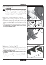
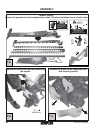
Replacement of pulleys
Notes for replacement of pulleys, if necessary.
• Unscrew the screws (M, Fig. 60) and remove the
protective casing.
• Loosen the belt tensioner completely (N, Fig. 60).
• Remove the belts.
To replace the driving pulley (O, Fig. 61), turn it
counterclockwise; viceversa, turn the driven pulley (P, Fig.
61) clockwise.
Fig. 61
Fig. 60
M
N
O
P
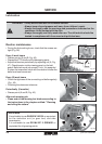
ATTENTION
It is absolutely essential to disengage the tractor
pto, lower the mowing machine, switch off the
tractor, ensure that this is at a complete standstill
and remove the key before servicing, adjusting
the implement for work. All assembly operations
must be carried out on a work bench.