


13
p/n GH 19502091
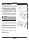
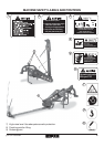
INSTALLING
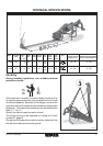
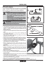
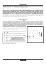
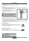
Stability of sickle bar and tractor during transport
When a sickle bar is coupled to a tractor, so becoming an integral part of it for the purposes of road
travel, the stability of the sickle bar-tractor complex may change and cause driving or operating difficulties
(rearing up or side-slipping of the tractor). The condition of equilibrium can be restored by placing a
sufficient number of ballasts on the front of the tractor so that the weights on the two tractor axles are
distributed sufficiently evenly. To work in safety the instructions given in the highway code should be
followed; these prescribe that at least 20% of the weight of the tractor alone should be borne by the front
axle and that the weight on the arms of the hoist should not be more than 30% of the weight of the tractor
itself. These factors are summarized in the following formulas:
Z > (M x s)-(0.2 x T x i)
(d+i)
The amount of ballast that should be applied according to the formula is the minimum required for circulation
on the road. If for reasons of tractor performance or to improve the set-up of the sickle bar during operation
it is thought necessary to raise these values, please refer to the registration document of the tractor to
check its limits. When the formula for calculating the ballast gives a negative result it will not be necessary
to add any weight. In any case, as long as the limits of the
tractor are respected, a suitable quantity of weights may be
applied in order to ensure greater stability during travel. The
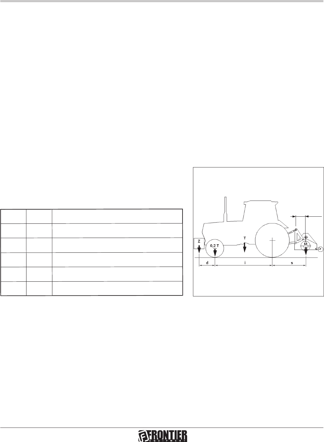
symbols have the following meanings:
M
Kg
Mass weighing on arms off hoist with full load
(Technical data table)
T
Kg
Mass of tractor
Z
Kg
Total mass of ballast
i
m
Tractor wheelbase, that is, the horizontal
distance between the tractor axles
d
m
Horizontal distance between the centre of gravity
of the ballast and the front axle of the tractor
s
m
Horizontal distance between the centre of gravity of
the operating machine and the back axle of the tractor
16
9
/64
inches
Fig. 14
(please see Fig. 14 for reference):