


11
p/n GH 19502091
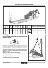
INSTALLING
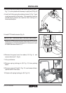
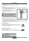
3. Hook the oscillating arms of the tractor to pins (E and F,
Fig. 7). Lock in place with the snap-in split pins (G Fig. 8)
4. Lock the lift links using the relative chains (H, Fig. 7) and
couplings parallel to the tractor. This operation must be
carried out to prevent the machine from moving in a
horizontal direction.
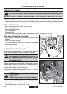
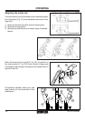
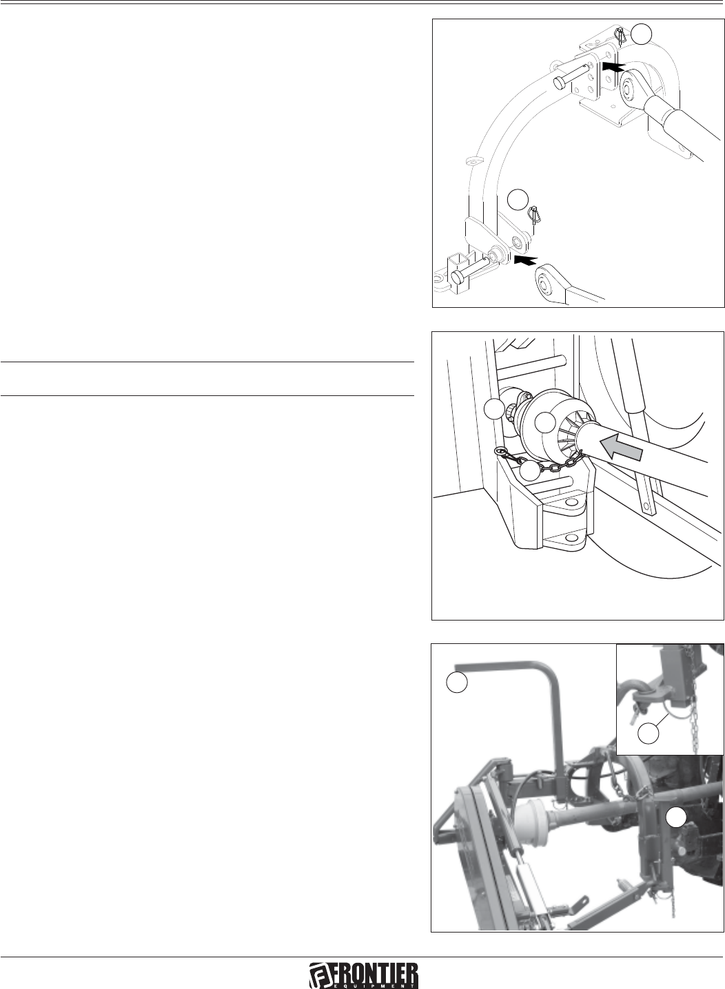
5. Install PTO shaft to tractor (Fig. 9).
IMPORTANT: Sickle bar MUST BE level front to rear.
Make sure PTO shaft is locked on the tractor PTO prior to
engagement (I). Check that the guard (L) is free to turn and
fix it with the relative latch (L1).
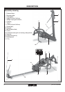
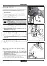
6. Remove the guard over the cutters (16, Fig. 4) and
remove the tirant (7, Fig.4).
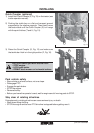
7. Lift-up sickle bar.
8. Remove spring locking pin (M, Fig. 10) from parking
stand.
9. Remove support (N and O, Fig. 10) and remount them,
upside-down in their seat .
10.Fasten with spring locking pin (M, Fig. 10).
M
N
O
L
I
G
D
Fig. 10
Fig. 9
Fig. 8
.
L1