31
p/n GH 19502091
SERVICE
Extra maintenance
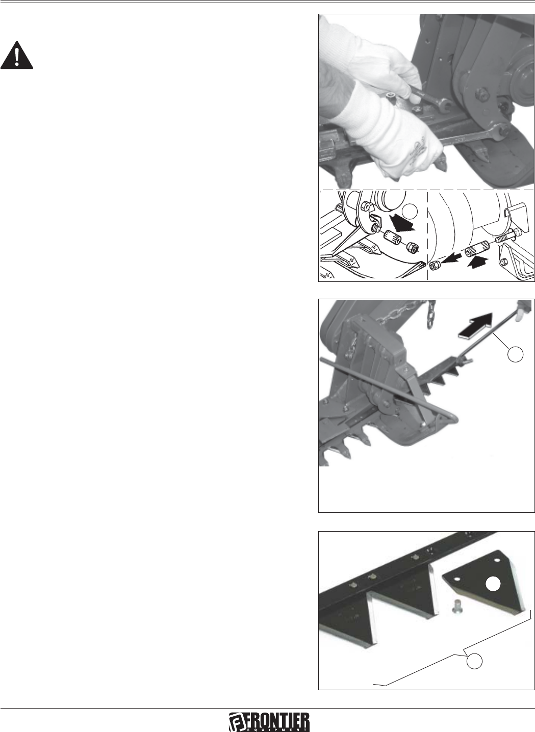
Fig. 57
Fig. 56
H
Fig. 55
I
L
J
Replacement of sections (J fig. 57)
• With the implement resting on the ground, open the cutter
bar.
• Remove the expansion pin (H, Fig. 55) and slide out the
section-holding bar (Fig. 56).
• Remove the damaged section using a pin punch (7 Fig. 4
on page 6).
• Rivet a new section with the rivets provided (J Fig. 57).
• Insert the section-holding bar and lock it in place with the
expansion pin.
ATTENTION
It is absolutely essential to disengage the tractor
pto, lower the mowing machine, switch off the
tractor, ensure that this is at a complete standstill
and remove the key before servicing, adjusting
the implement for work. All assembly operations
must be carried out on a work bench.
Replacement of section-holding bar (L fig. 57)
• With the implement resting on the ground, open the mowing
bar.
• Remove the expansion pin (H, Fig. 55) and pull out the
section-holding bar (Fig. 56) with the hooking tie rod (I Fig.
56).
• Insert the new section-holding bar and lock it in place with
the expansion pin. Lubricate the cutters with very viscous
oil during the assembly phase.


