


HV-G Instruction Manual Page 56
17 Options
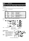
17.1 RS-232C / Relay output / Buzzer (OP-03)
Replacing RS-232C interface with this option, refer to “ RS-232C Serial Interface” for its
specification.
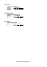
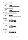
The following option cables can be used, when you do not use the relay output.
AX-KO557A, AX-KO1786-200
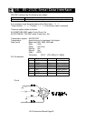
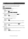
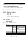
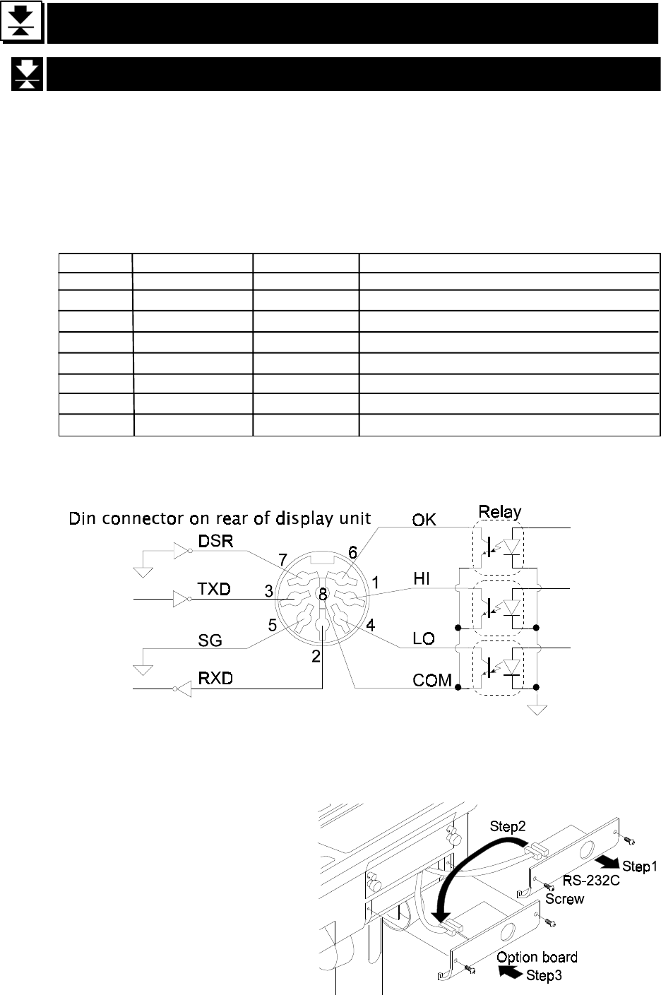
Pin connections
Mating connector DIN 8pin, JA:TCS0586 (of accessory pack)
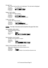
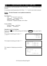
Circuit
Relay Solid-state-relay Maximum voltage DC50V
Maximum current DC100mA
Maximum ON resistance 8 Ω
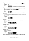
Pin No. Signal name Direction Description
1 HI Output Relay output of HI
2 RXD Input Receive data
3 TXD Output Transmit data
4 LO Output Relay output of LO
5 SG - Signal ground (RS-232C)
6 OK Output Relay output of OK
7 DSR Output Data set ready
8 COM - Relay common terminal
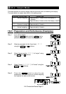
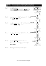
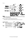
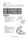
Installing OP-03
Step 1 Remove two screws that
attach the RS232C board on
the rear of the display unit.
Remove the RS232C board.
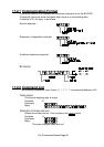
Step 2 Switch the connections.
Step 3 Insert the option board into the
display unit and afix with
screws