Teledyne API Model 401 O
3
Photometric Calibrator Instruction Manual, 01124, Rev. J2
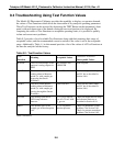
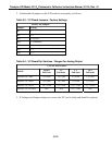
2. Confirm that all jumpers on the V/F board are set properly, as follows:
Table 9-3: V/F Board Jumpers - Factory Settings
Factory Set Jumpers
Jumper Setting
B1 1
B2 1-2
B12 3-4 (0-5V)
B14 2-3 (Enabled)
B15 Set to match power line frequency
JP1 1-2
JP2 1-2
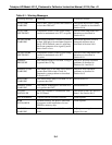
Table 9-4: V/F Board Dip Switches - Ranges For Analog Output
User Set DIP Switches
Switch
100 mV
Full Scale
1 V
Full Scale
5 V
Full Scale
10 V
Full Scale
S1(DAC 0)= “REC” 1,6 = ON 1,5 = ON 1,4 = ON 1,3 = ON
S2(DAC 1)= “DAS” 1,6 = ON 1,5 = ON 1,4 = ON 1,3 = ON
S3(DAC 2)=”TEST” 1,6,7 = ON 1,5,7 = ON 1,4,7 = ON 1,3,7 = ON
S3(DAC 2)=”O3 GEN” N/A N/A 1,4,7 = ON N/A
3. If Voltages and Jumper settings are correct, the V/F card is faulty and should be replaced.
9-12


