


Teledyne API Model 401 O
3
Photometric Calibrator Instruction Manual, 01124, Rev. J2
1.6.3 Pneumatic System
The Model 401 Photometric Calibrator is equipped with a compression pump to deliver up to 5
L/MIN for ozone generator system. It is also equipped with a second pump capable of pulling
800 cc/min across a critical flow orifice. This allows a smooth, stable flow of sample through the
Photometer.
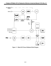
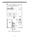
Compressed air is delivered through a charcoal scrubber. While one path is used as zero air
reference, the other path of same zero air is used to generate the stable ozone output. This will
ensure reliable ozone output as well as proper Photometer operation. Please see Figure 1-1 for
flow diagram and Figure 1-5 for pneumatic connections.
NOTE
The photometer output varies linearly with pressure and
temperature. Temperature and pressure compensation is
done automatically.
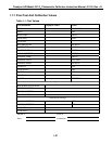
A critical flow orifice is used to control the sample flow. The orifice is a precision-drilled
sapphire jewel protected by a 20 micron sintered filter. The critical flow orifice never needs
adjustment and maintains precise flow control as long as the ratio of the up-stream to down-
stream pressures is greater than 0.53 (sonic flow conditions).
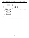
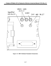
1.6.4 Exhaust Connections (See Figure 1-5)
A single 1/4" O.D. tube should be connected from the Analyzer sample exhaust to an area
outside of the room the analyzer occupies. The maximum length of the exhaust line should not
exceed 30 feet.
1.6.5 Output Flow Adjustment
The flow rate of gas supplied to the output manifold can be changed by adjusting the internal
pressure regulator located on the top of the optical bench (see Figure 1-7). The output flow, O
3
FLOW, can be read on the front panel test functions. Adjust this flow rate to provide a minimum
of 1 LPM for each analyzer being calibrated plus 1 LPM for the internal photometer in the
M401. For example, when calibrating one analyzer the O
3
flow rate should be set to at least 2
LPM.
1-16